Welcome to StructuPro
StructuPro is a comprehensive structural engineering application designed to streamline your design workflow. Whether you're analyzing beams, designing steel members or connections, our tools provide accurate calculations with detailed reporting.
Beam Calculator
Calculate internal forces, moments, displacements, and reactions for beams under various loading conditions. Supports multiple load types and support conditions.
- Point loads, distributed loads, and moments
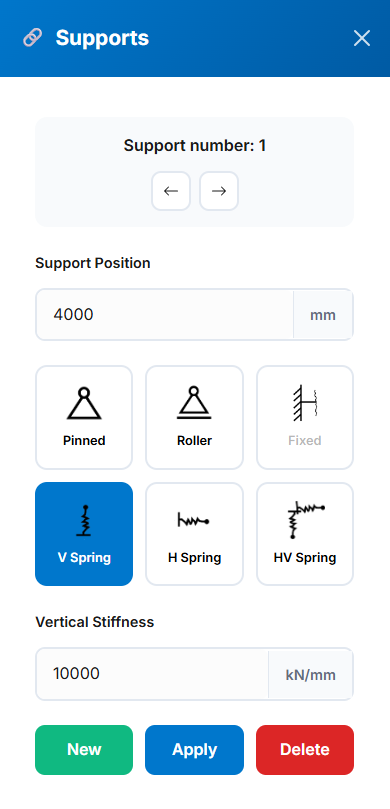
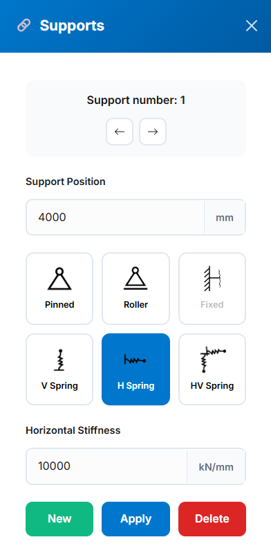
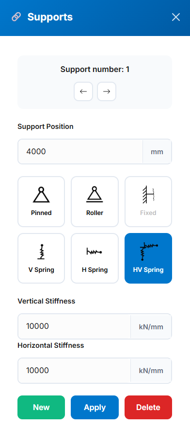
- Pinned, roller, fixed, and spring supports
- Real-time visualization of results
- PDF export with detailed diagrams
Steel Member Design
Design steel segments or members according to NZS3404 and AS4100 standards. Perfect for complex multi-segment analysis.
- Multi-segment design capability
- Three report types: Summary, Standard, Detailed
- Critical segment identification
- Visual representation of member/segment design and segments end conditions
- Exports design results in PDF format
- Automatically calculates relevant design factors
Connection Design
Comprehensive suite of 12+ steel connection design tools fully compliant with SCNZ Steel Connections Design Guide (SCNZ 14.1-2007).
- 12+ connection types including simple, moment, and splice connections
- Full compliance with SCNZ 14.1-2007 and AS/NZS standards
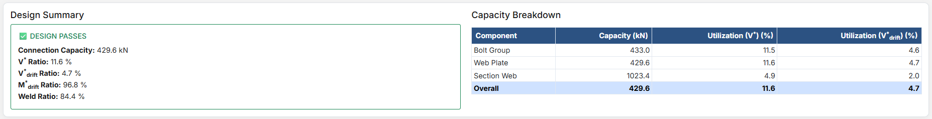
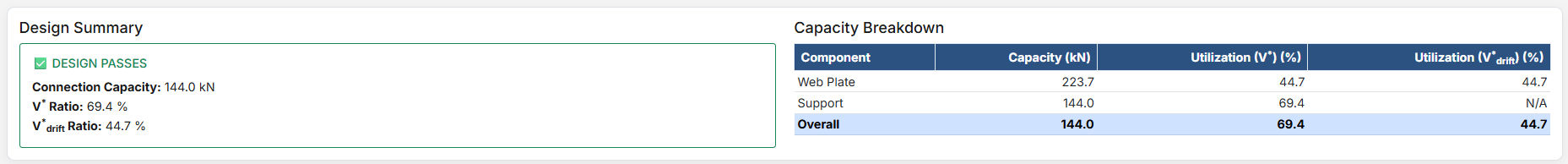
- Real-time design checks with pass/fail indicators
- Comprehensive PDF reports with all calculations
Quick Start Guide
- Choose your module: Beam Calculator or Member Design
- Enter project details and specifications
- Define geometry, supports, and loading conditions
- Run analysis and review results
- Export comprehensive PDF reports
Quick Start Guide
Getting Started: This guide will walk you through the basic workflow of the modules.
Beam Calculator Workflow
- General Setup: Define beam length, material properties, and section type
- Add Supports: Place supports along the beam with appropriate restraints
- Apply Loads: Add point loads, distributed loads, or moments
- Analyze: Run the analysis to generate force and deflection diagrams
- Export: Download results as a PDF report
Member Design Workflow
- Project Details: Enter project information and metadata
- Segment Details: Define member geometry and segment properties
- Forces: Input internal forces either automatically or manually
- Design: Run the design check according to selected standard
- Results: Review capacity ratios and export documentation
Connection Design Workflow
- Project Details: Enter project information, metadata, and loading parameters
- Member Properties: Select section type, grade, and dimensions for beam/column
- Plate Details: Specify plate grade, dimensions, and geometry
- Bolt Configuration: Define bolting category, sizes, spacing, and layout
- Weld Details: Select electrode type and weld sizes (if applicable)
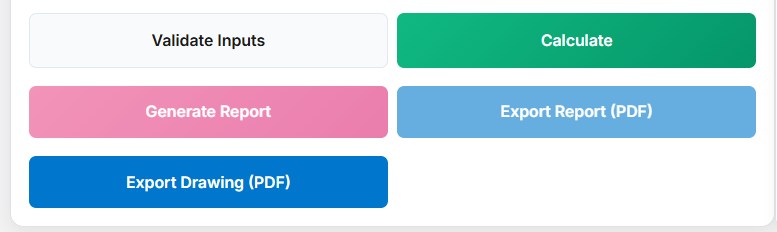
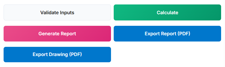
- Design: Validate inputs and run calculations per SCNZ standard
- Results: Review capacity ratios, generate reports, and export documentation
Project Details
The Project Details section captures essential information that will appear in your final documentation.
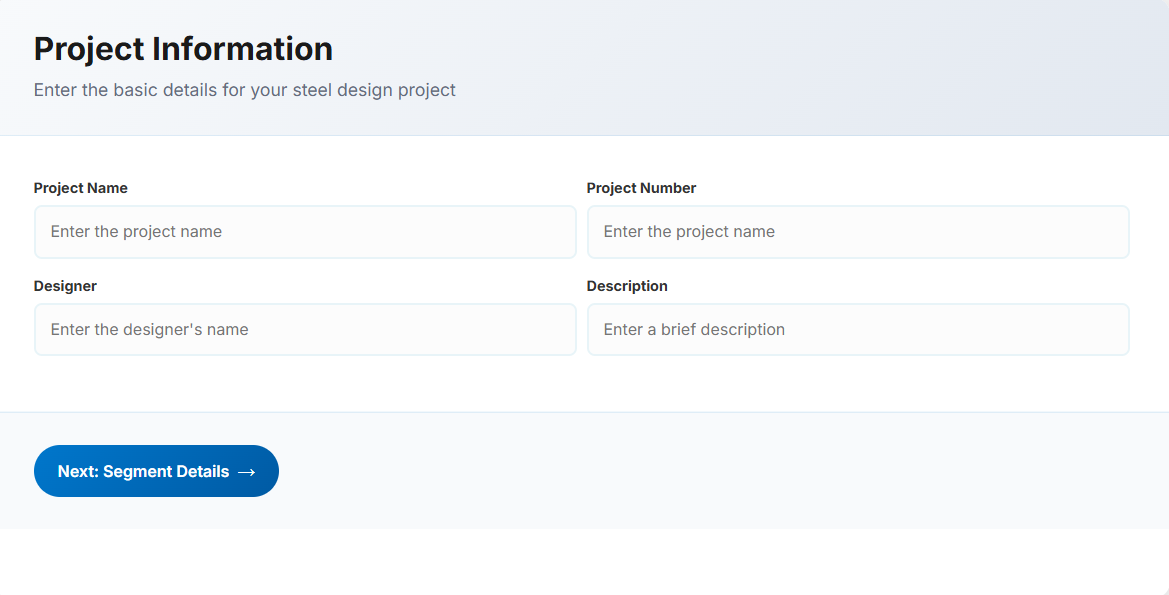
Input Fields
- Project Name: Enter the name of the project. This helps identify the design file
- Project Number: Unique code or number for project tracking and reference
- Project Designer: The person responsible for the segment design
- Description: A brief overview of the project or design purpose
Tip: All fields are optional but recommended for professional documentation. The information entered here will appear in the header of your PDF reports.
Segment Details
a. General Configuration
This section defines the geometry and properties of the steel member or segment. Key inputs include member length, section type, design reference, and other specifications.
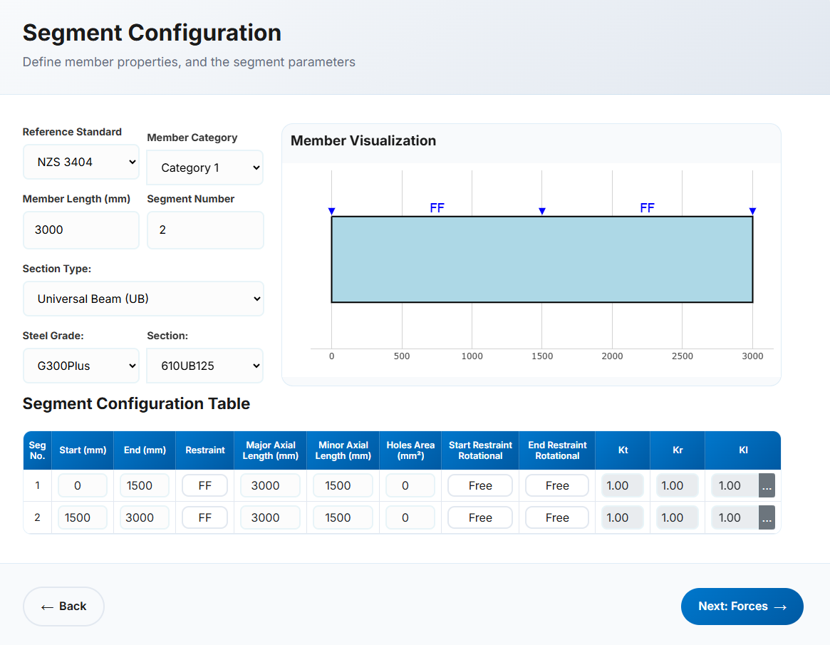
- Reference: Select either NZS3404 or AS4100 as the design standard.
- Member Category: Automatically populated for NZS3404. This field is hidden when AS4100 is selected. Used to verify section geometry per Clause 12.4.
- Member Length: Define the total member or segment length in millimetres (mm).
- Segment Number: Enter 1 for a single segment or the number of segments for a multi-segment member.
-
Section Type: Common New Zealand and Australian sections are available, including:
- UB (Universal Beam) – Grade G350 and G300+
- UC (Universal Column) – Grade G350 and G300+
- CHS (Circular Hollow Section) – Grade G250 and G350
- RHS (Rectangular Hollow Section) – Grade G350 and G450
- SHS (Square Hollow Section) – Grade G350 and G450
- PFC (Parallel Flange Channel) – Grade G350 and G300+
- TFB (Tapered Flange Beam) – Grade G350 and G300+
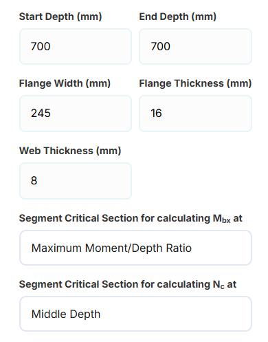
- CWB (Custom Welded Beam) – Various grades.
For CWB sections, the application allows the user to input the
start and end depths, flange width, and
flange and web thicknesses.
The user can also select the critical segment section used for
calculating Mbx or Nc.
-
When calculating Mbx, the critical section may be selected as:
- Maximum moment-to-depth ratio
- Minimum depth
- Maximum depth
- Middle depth
-
When calculating Nc, the critical section may be selected as:
- Minimum depth
- Middle depth
- PB, EB, HB, HCB, HCBC, HCC, HP, NB, BP, SB, SC, LB, WS – Welded steel sections in Grade G300M
- Steel Grade: Automatically populated based on section type.
- Section: Select from a list based on the chosen section type.
b. Segment Specifications
The number of rows corresponds to the number of segments. Each segment can have unique specifications.
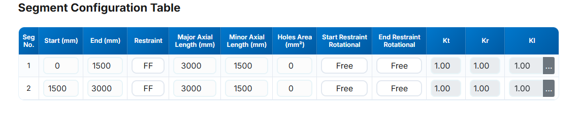
Restraint Conditions
- Seg No: Segment number identifier.
- Start (mm): Distance from the beginning of the member.
- End (mm): End position relative to the start of the member. Must not be less than 0 or less than the previous segment end.
-
Restraint: End restraints as per Clause 5.4.3 of AS4100/NZS3404. No distinction is made between start or end, as each segment is treated independently.
- FF: Full restraint at both ends
- FL: Full restraint at one end, lateral restraint at the other
- LL: Lateral restraint at both ends
- FU: Full and unrestrained ends
- FP: Full and partial restraint
- PL: Partial and lateral restraint
- PU: Partial and unrestrained
- PP: Partial restraint at both ends
- Major Axis Length (mm): Length for bending about major axis (x-x). Defaults to member length.
- Minor Axis Length (mm): Length for bending about minor axis (y-y). Defaults to segment length.
- Hole Area (mm2): Total hole area within the segment.
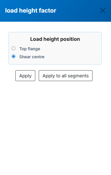
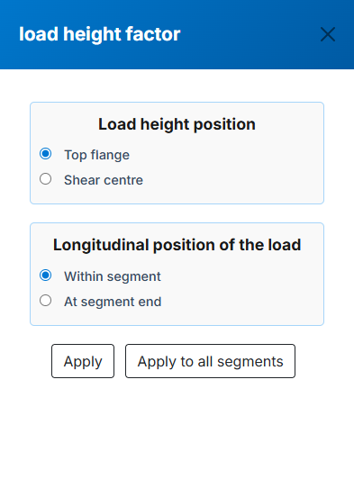
- Start/End Restraint Rotational: "Free" or "Fixed" per Clause 5.4.3.4, affecting rotation restraint factor (kr).
- Kt : Twist restraint factor. Automatically calculated; not editable.
- Kr : Rotational restraint factor. Automatically calculated; not editable.
- Kl : Load height factor for gravity loads. Calculated from load position inputs. Press the adjacent button to view the selection menu:
Forces Input
In this tab, Internal forces in the segment or member can be imported in twe ways, "Automatic Calculation" and "Manual for Each Segment". The first method is usually used
for a member contains several segments. Instead of extracting the internal forces for each segment from the analysis engine, they can be imorted in several stations regardless of
the number or location of the segments. The software automatically calculates the internal forces for each segment.
The second method is usually used when the internal forces of each segment are available.
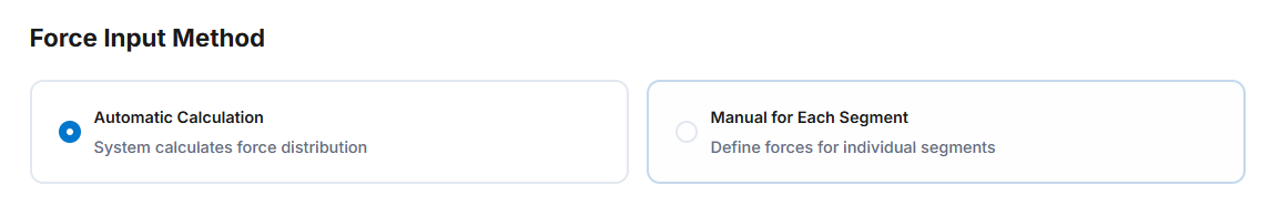
Method 1: Automatic Calculation
Ideal for members with multiple segments. Input forces at various stations and the software interpolates values for each segment.
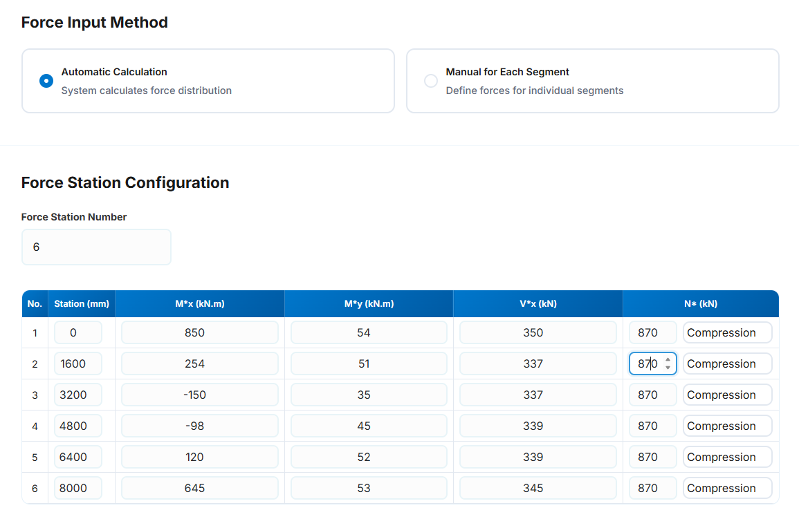
Input Parameters
-
Force Station Number: The number of the force stations. It is not same as the segment number and can be different based
on the force diagram changes throughout the member. Most of analysis platforms provide the forces at specified stations in the member which can
be used easily in here. We are trying to provide some features to get these forces automaticaly from the popular analysis platforms.
- No: The station number in each row.
-
Station (mm): The station location in each row in mm from the start of the member. The station location
should be greater than the previous one and less than the next one. The maximum value is the length of the member.
-
Mx* (kN.m): The design bending moment about the x-axis (major-axis) in kN.m for the corresponding station.
This value can be negetive.
-
My* (kN.m): The design bending moment about the y-axis (minor-axis) in kN.m for the corresponding station.
This value can be negetive.
- Vx* (kN): The design shear force (major-axis) in kN for the corresponding station. This vale is positive
- N* (kN): The design axial (Compression or Tension) force in kN for the corresponding station. This value is positive
- The axial force type (Compresion or Tension) can be selected from the drop-down list.
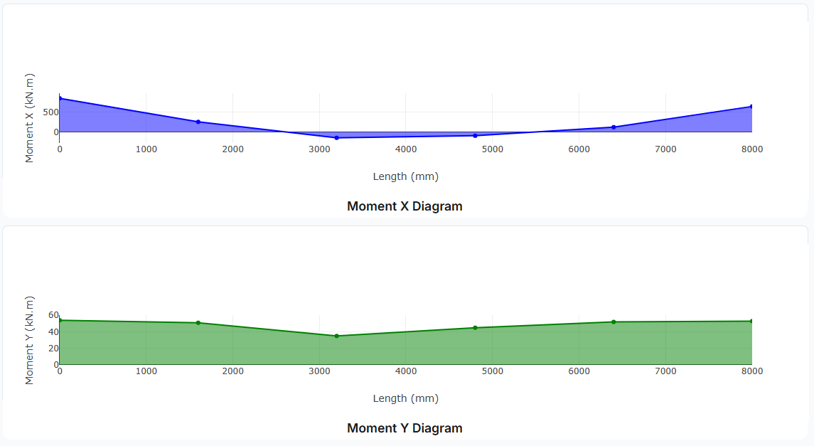
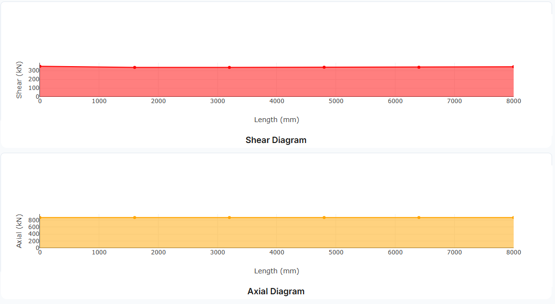
Visualization: Bending moment, shear force, and axial force diagrams are automatically generated to help verify your input.
Method 2: Manual Input
Direct input of maximum forces for each segment. Best when you have exact values from analysis software.
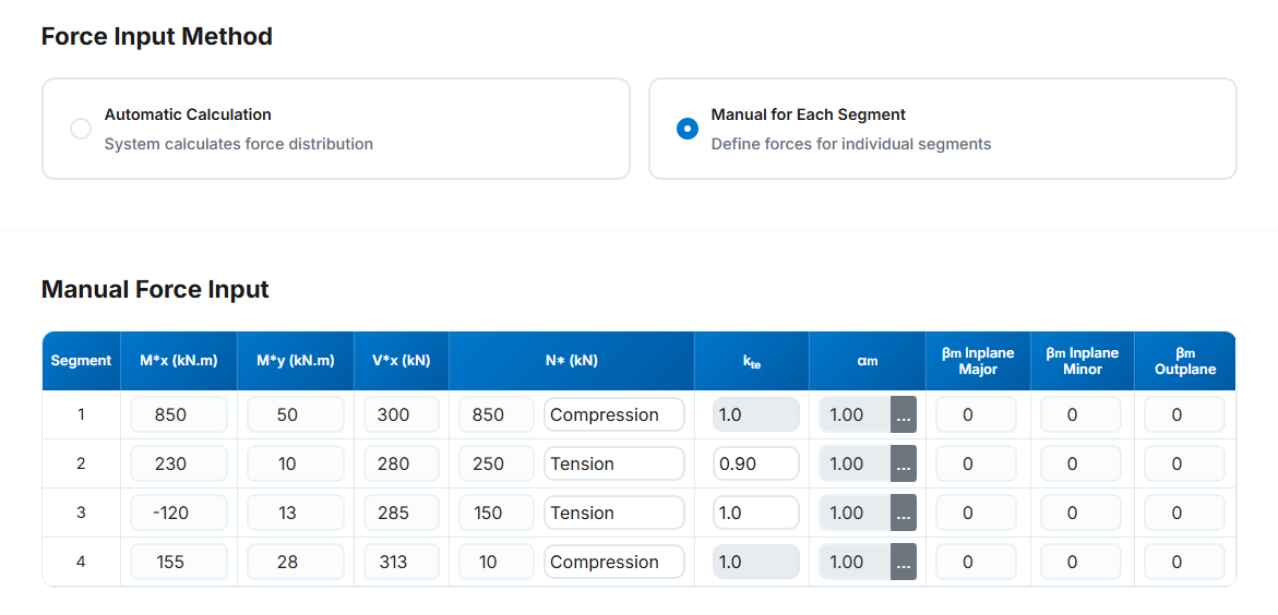
-
Segment: The segment number in each row.
-
Mx* (kN.m): The design bending moment about the x-axis (major-axis) in kN.m for the corresponding station.
This value can be negetive.
-
My* (kN.m): The design bending moment about the y-axis (minor-axis) in kN.m for the corresponding station.
This value can be negetive.
- Vx* (kN): The design shear force (major-axis) in kN for the corresponding station. This vale is positive
- N* (kN): The design axial (Compression or Tension) force in kN for the corresponding station. This value is positive
- The axial force type (Compresion or Tension) can be selected from the drop-down list.
- kte: Correction factor for distribution of forces in a tension segment according to clause 7.3 of NZS 3404 and AS 4100. This is active once the tension is selected as axial force type.
-
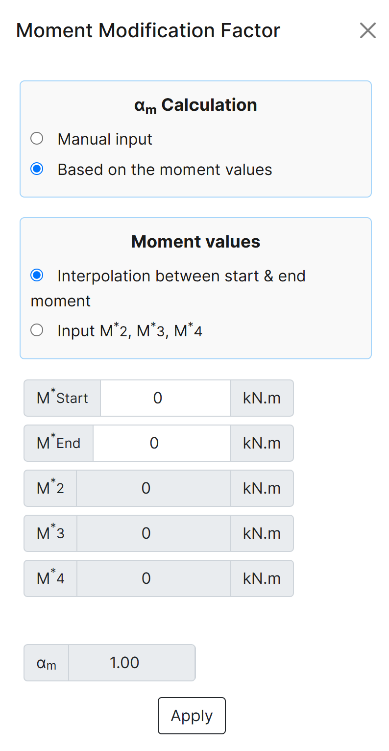
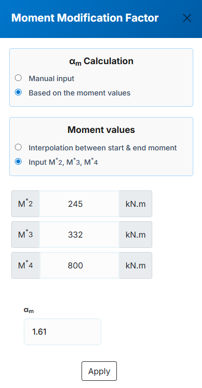
αm :The moment modification factor as per clause (5.6.1.1.1b) of NZS 3404 and AS 4100. The user can
specified this value in three ways that one of them is manual input and the other two are automatic based
on the input moment values which can be achived by the button next to the αm non editable value in each segment row.
a. Manual input: In this method the user can input the αm value manually then apply it for the corresponding segment.
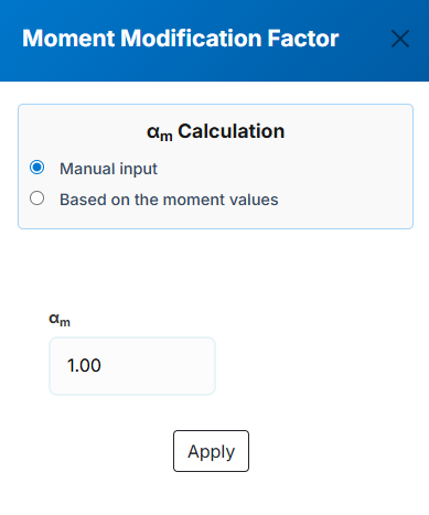
b. Based on the input moment values - Interpolation between start & end moment: In this method the user specifies the major axis bending moments for the start and end
of the segment and the software will calculate the αm value for the corresponding segment based on the interpolation between the start and end moments which specifies
M2*, M3*, M4* values to be used in (Eq. 5.6.1.1(2)) of NZS 3404 and AS 4100.
c. Based on the input moment values - Input M2*, M3*, M4*: In this method the user specify M2*, M3*, M4*
and the software will calculate the αm value based on the (Eq. 5.6.1.1(2)) of NZS 3404 and AS 4100 for the corresponding segment.
-
βm In plane Major : The ratio of smaller to larger bending moment at the ends of a member for inplane major bending. Should be imported manualy and it is only
used in alternative design provision
-
βm In plane Minor:The ratio of smaller to larger bending moment at the ends of a member for inplane minor bending. Should be imported manualy and it is only
used in alternative design provision
-
βm Out of Plane:The ratio of smaller to larger bending moment at the ends of a member for out of plane bending. Should be imported manualy and it is only
used in alternative design provision
Design Results
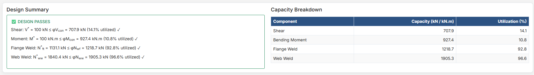
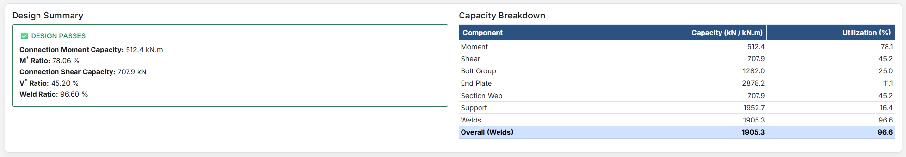
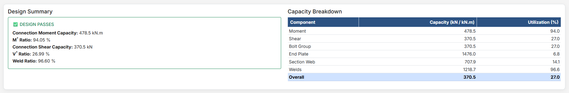
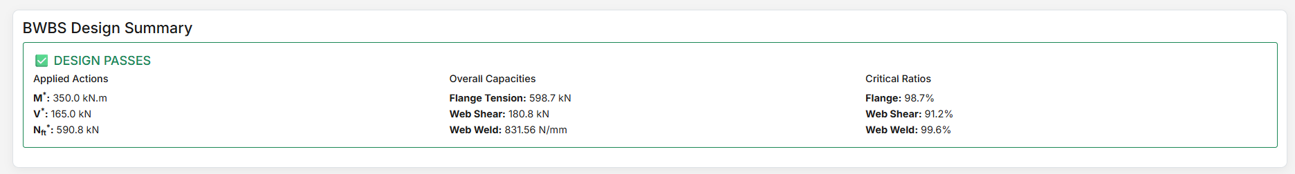
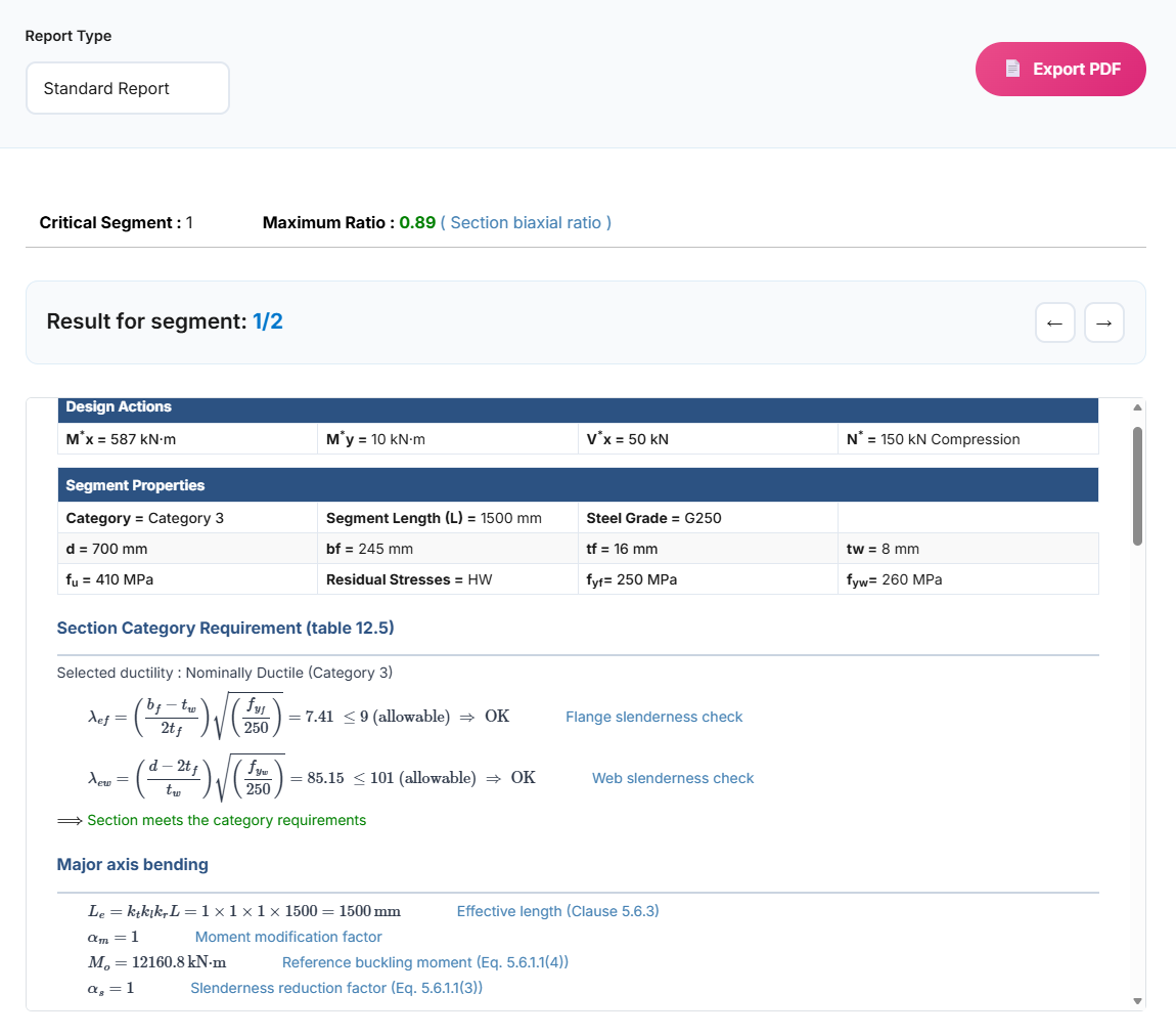
After clicking "Design", comprehensive results are displayed with multiple reporting options.
Report Types
Summary Report
High-level overview showing pass/fail status and critical capacity ratios. Perfect for quick compliance checks.
Standard Report
Balanced detail with key equations and intermediate values. Suitable for most documentation needs.
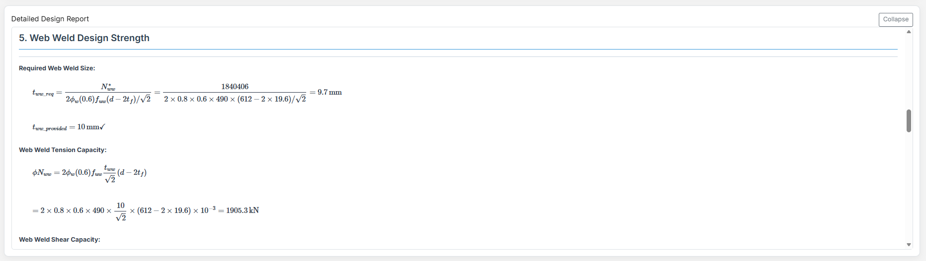
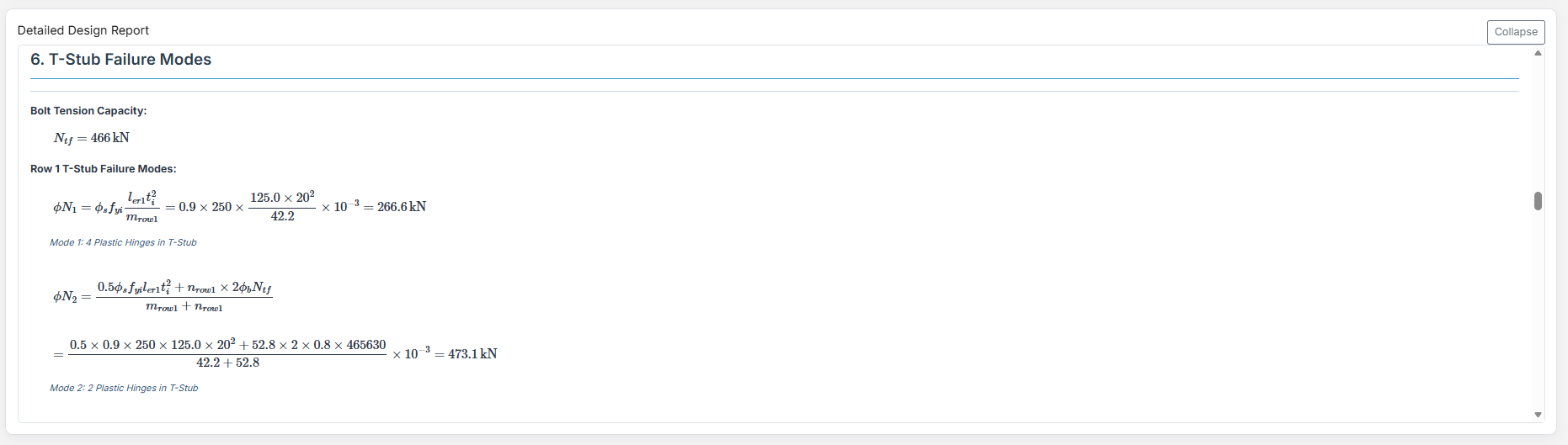
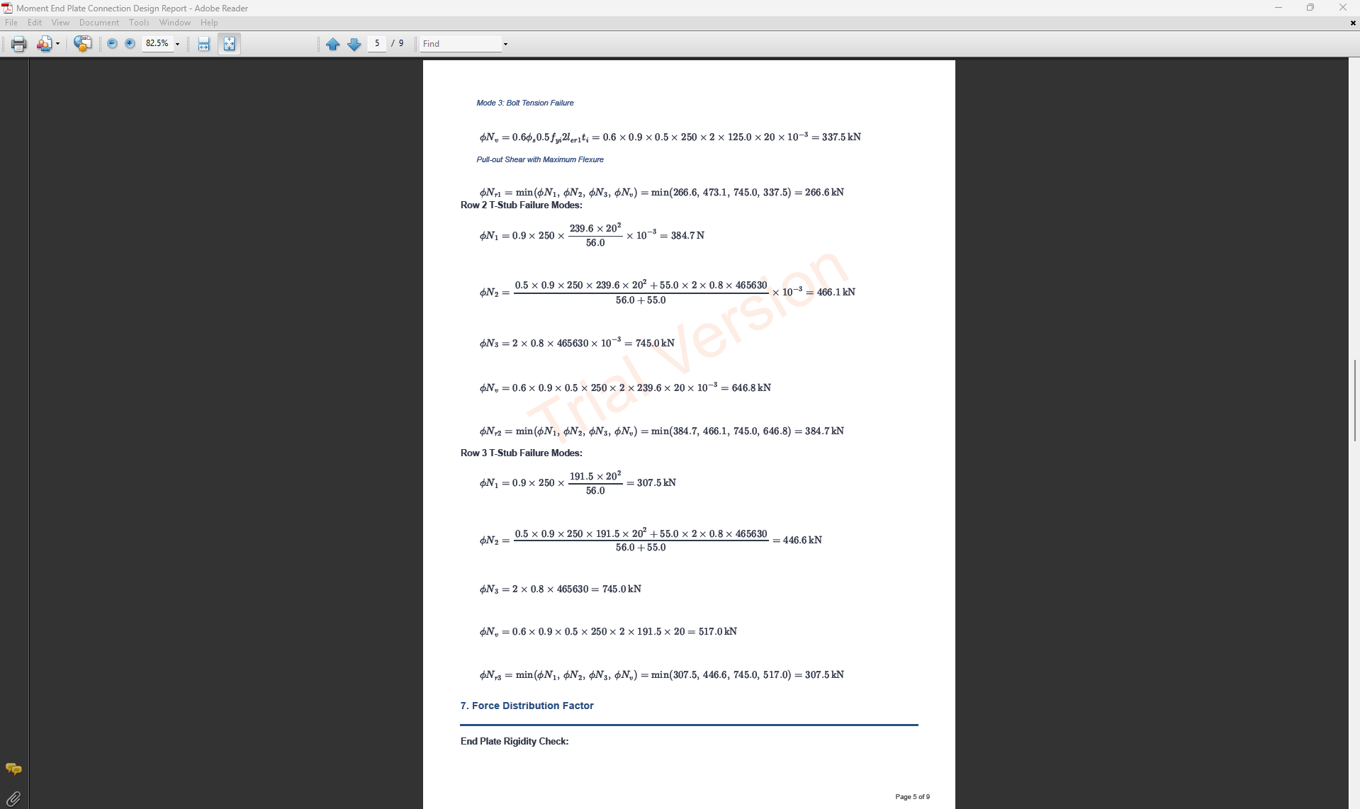
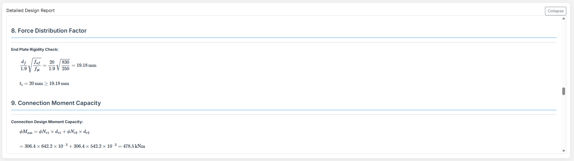
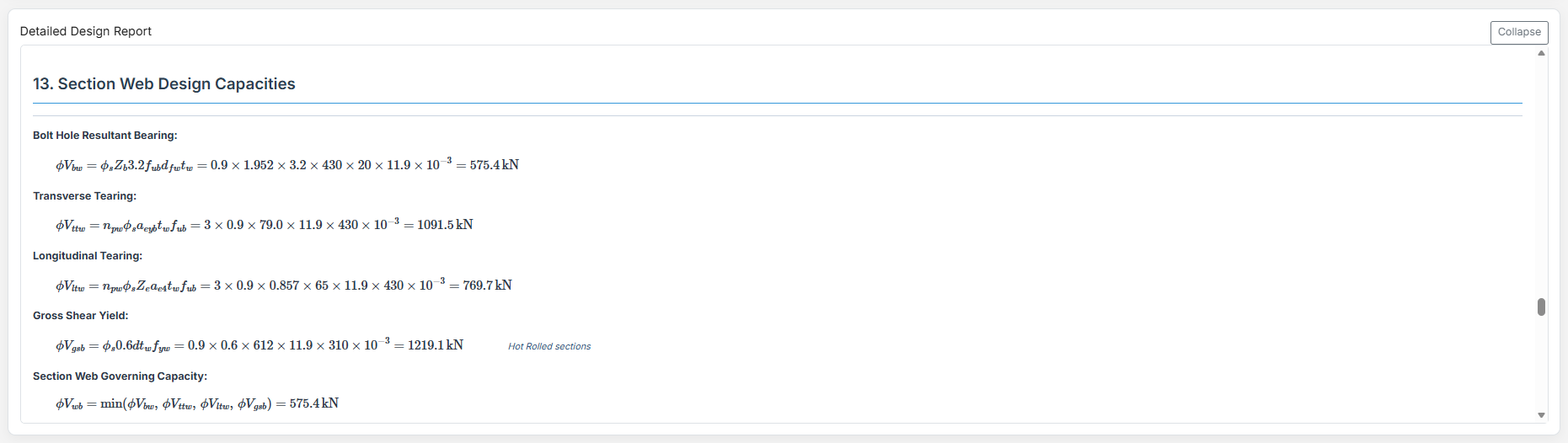
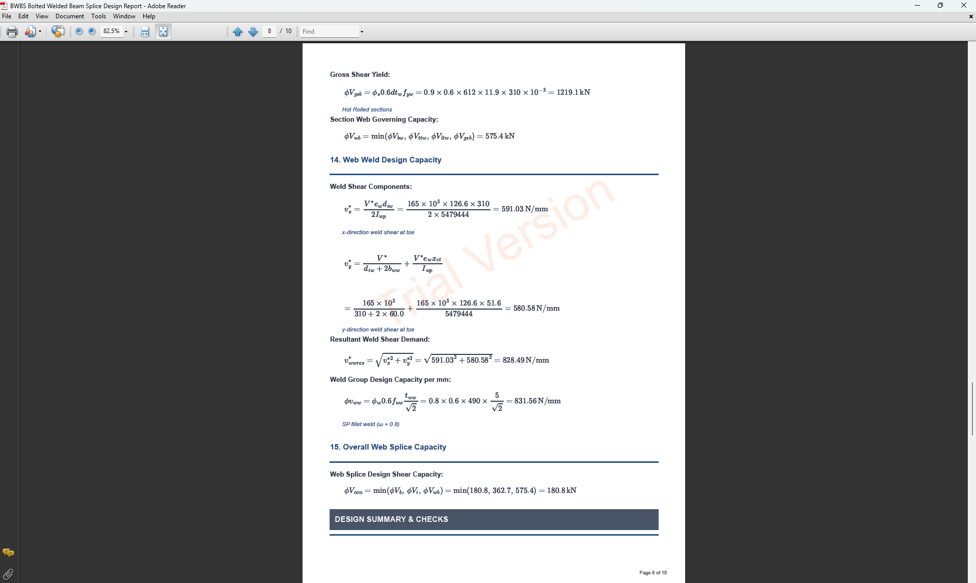
Detailed Report
Complete step-by-step calculations with all equations in scientific notation. Ideal for verification and learning.
Key Features
-
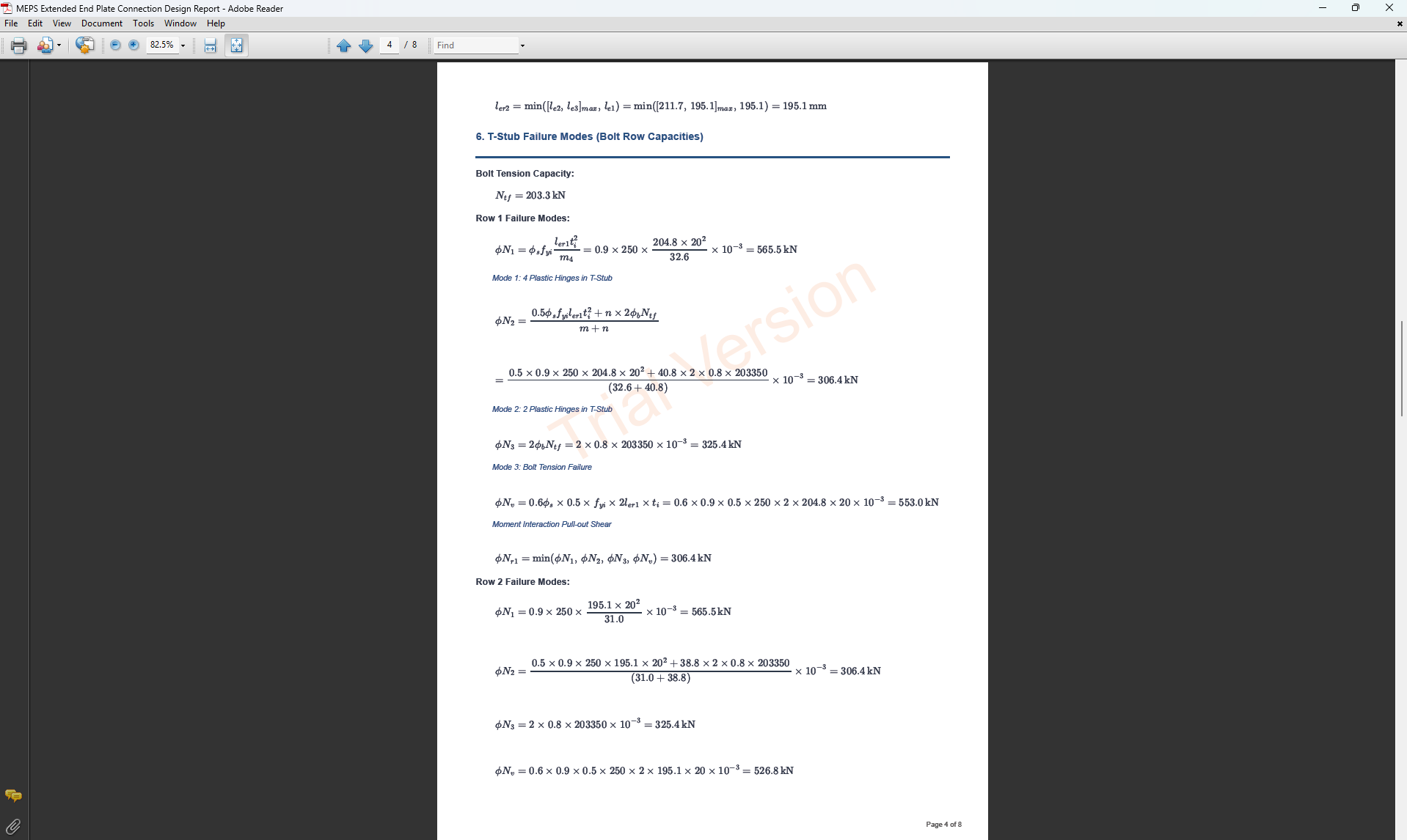
PDF Export: The user can export the selected design report as a PDF file. By default, the file is saved to the user's downloads folder, but this location can be changed.
-
Critical Segment: Displayed at the top of the report, it identifies the critical segment when multiple segments exist, along with the highest ratio and the cause of that ratio.
-
Result for segment: Indicates which segment the displayed results relate to. Users can navigate to reports for other segments using the right and left arrows.
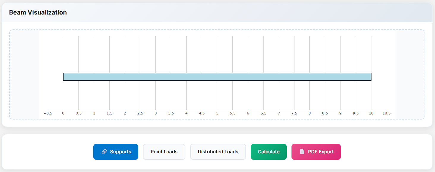
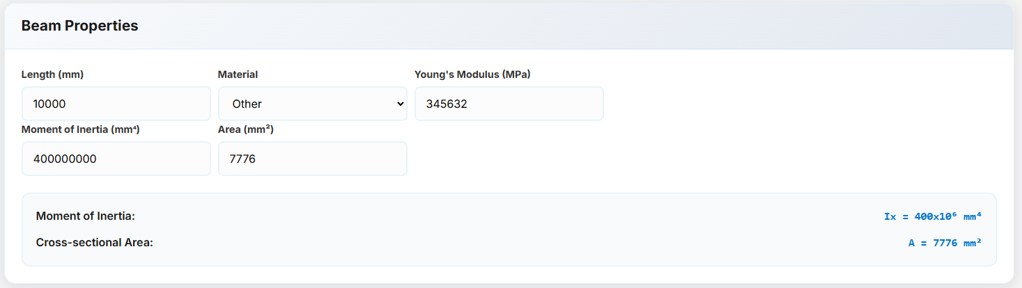
Beam Calculator - General Setup
Configure the basic properties of your beam including material, geometry, and section properties.
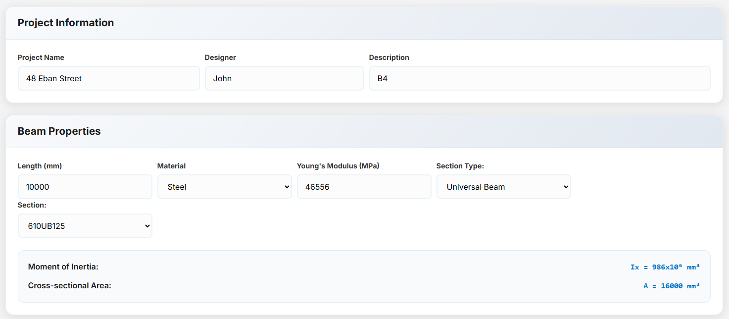
Project Information
- Project Name: The title assigned to the project.
- Designer: The name of the individual responsible for designing the project.
- Description: A brief summary outlining the scope and purpose of the project.
- Length: The total length of the beam/member.
- Material: The type of material used in the beam, which can be steel, concrete, or other materials.
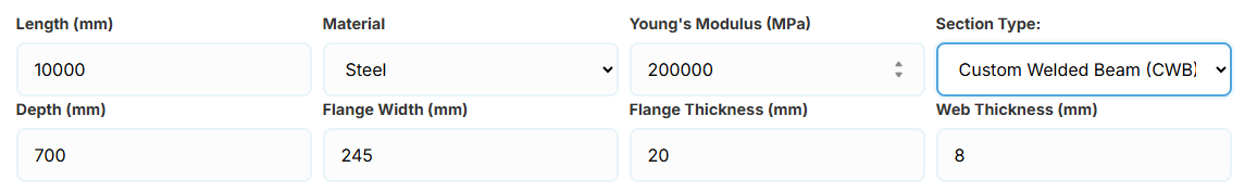
Material Options
a. Steel Sections
Young's Modulus: The Young's modulus of the steel material.
Section Type: A list of common steel sections used in New Zealand and Australia:
- UB (Universal Beam) - Grades G350 and G300+
- UC (Universal Column) - Grades G350 and G300+
-
CWB (Custom Welded Beam) - Various grades.
- CHS (Circular Hollow Section) - Grades G250 and G350
- RHS (Rectangular Hollow Section) - Grades G350 and G450
- SHS (Square Hollow Section) - Grades G350 and G450
- PFC (Parallel Flange Channel) - Grades G350 and G300+
- TFB (Tapered Flange Beam) - Grades G350 and G300+
- PB (Perimeter Welded Beams) - Grade G300M
- EB (Equivalent Welded Beams) - Grade G300M
- HB (Heavy Welded Beams) - Grade G300M
- HCB (High Capacity Beams) - Grade G300M
- HCBC (High Capacity Beam-Columns) - Grade G300M
- HCC (High Capacity Columns) - Grade G300M
- HP (Welded 'H' Piles) - Grade G300M
- NB (Narrow Welded Beams) - Grade G300M
- BP (Welded Bearing Piles) - Grade G300M
- SB (Standard Welded Beams) - Grade G300M
- SC (Standard Welded Columns) - Grade G300M
- LB (Light Welded Beams) - Grade G300M
- WS (Wide Sections) - Grade G300M
Section: Automatically populated based on the selected section type. The user can then select a specific section from the list.
The moment of inertia and area are automatically calculated based on the selected section.
When CWB is selected, manual inputs for depth (d), flange width (bf), flange thickness (tf), and web thickness (tw) become available.
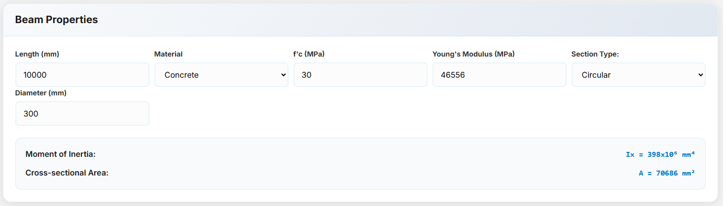
b. Concrete Sections
If the selected material is concrete, the following options are available:
f'c: The compressive strength of the concrete in MPa.
Young's Modulus: Automatically calculated based on f'c, but it can also be entered manually.
Rectangular Concrete Section: Enter the height and width of the section to calculate its properties.
 Circular Concrete Section: Enter the diameter of the section to calculate its properties.
 Other Concrete Section: Manually enter the moment of inertia and area for custom sections.
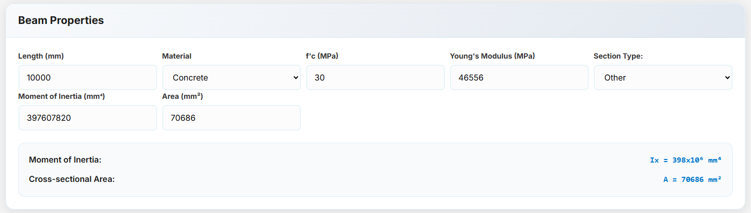
c. Other Materials
If the material is not steel or concrete, you can manually enter the Young's modulus, moment of inertia, and area.
Beam Calculator - Loads
This section allows you to add point loads by specifying their position along the beam, value, load type, and direction.
Point Loads & Moments
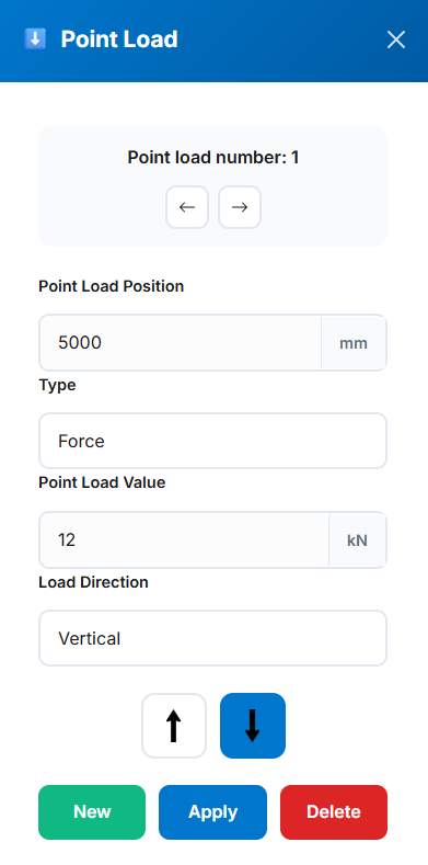
- Point Load Number: Automatically generated based on existing point loads. You can navigate through existing loads using the left and right arrow buttons.
- Point Load Position: Specifies the location of the point load on the beam in millimeters (mm).
- Type: Indicates the type of load. Options include Force or Moment.
- Point Load Value: The magnitude of the load in kilonewtons (kN) for forces or kilonewton-meters (kN·m) for moments.
- Load Direction: For forces, options include Vertical or Horizontal. For moments, choose Clockwise or Anticlockwise.
- Direction Arrows: Available only when the load type is set to Force. Use the arrows to specify direction—left or right for horizontal forces, and up or down for vertical forces.
Distributed Loads
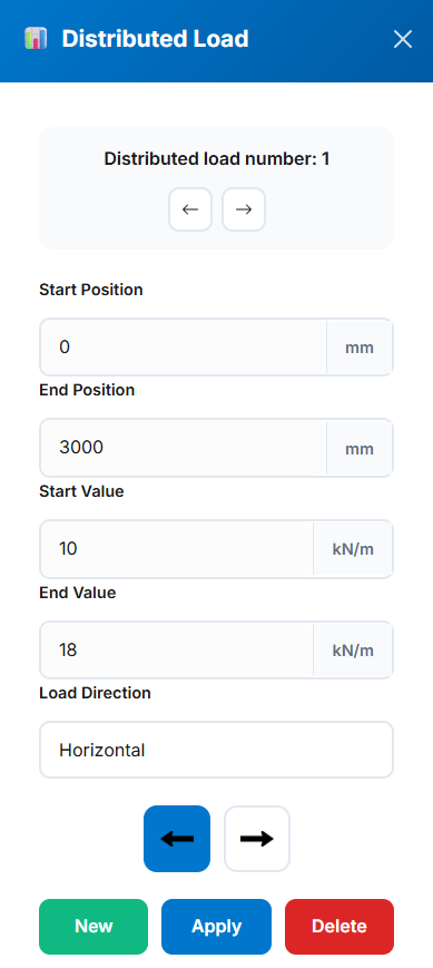
- Distributed Load Number: Automatically generated based on existing distributed loads. You can navigate through existing loads using the left and right arrow buttons.
- Start Position: Specifies the starting position of the distributed load on the beam, in millimeters (mm).
- End Position: Specifies the ending position of the distributed load on the beam, in millimeters (mm).
- Start Value: The value of the distributed load at the start position, in kilonewtons per meter (kN/m).
- End Value: The value of the distributed load at the end position, in kilonewtons per meter (kN/m).
- Load Direction: Defines the direction of the distributed load. It can be either Vertical or Horizontal.
- Direction Arrows: Used to specify direction—left or right when "Horizontal" is selected, and up or down when "Vertical" is selected.
Tip: Loads can be positive or negative. Visual indicators show direction on the beam diagram.
Actions
- New: Adds a new load. Once added, there is no need to press this button again unless you want to add another load.
- Apply: Applies the current load settings and adds it to the beam.
- Delete: Deletes the currently selected load and removes it from the beam.
Beam Calculator - Calculations & Export
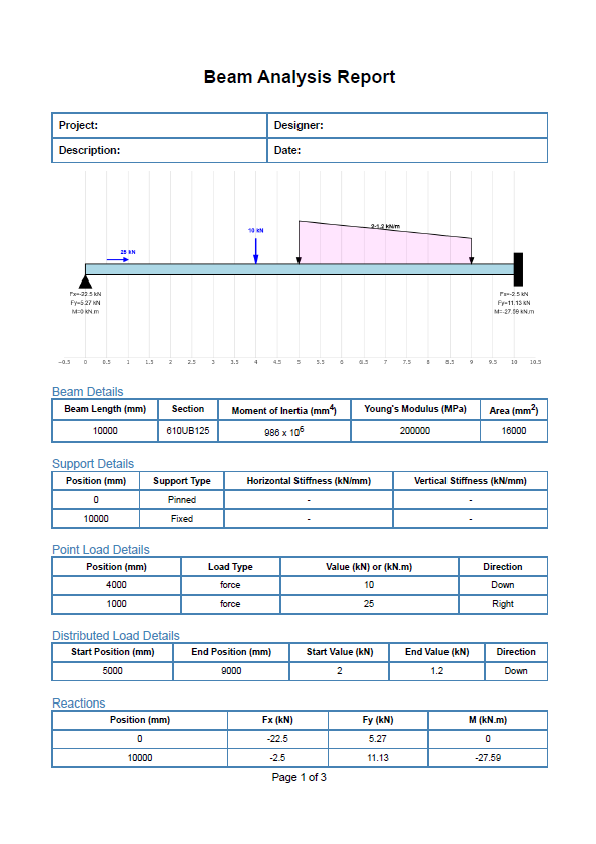
Press the Calculate button to compute reactions, internal forces, and deflections. Export results for documentation.
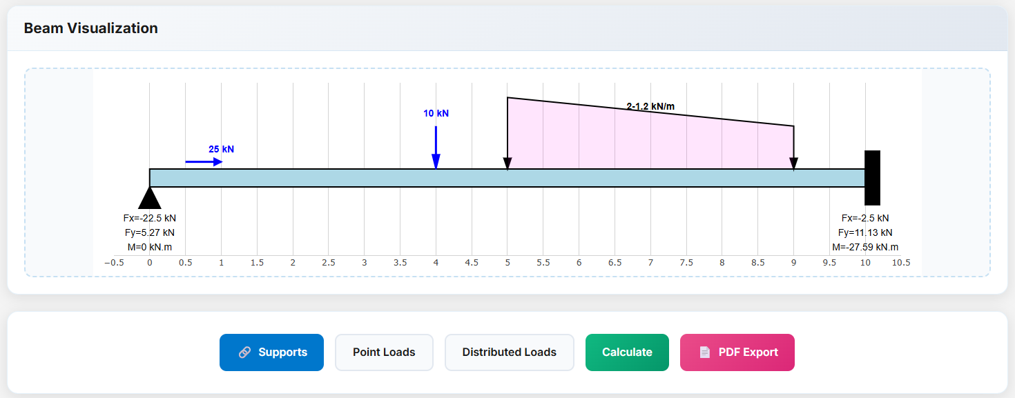
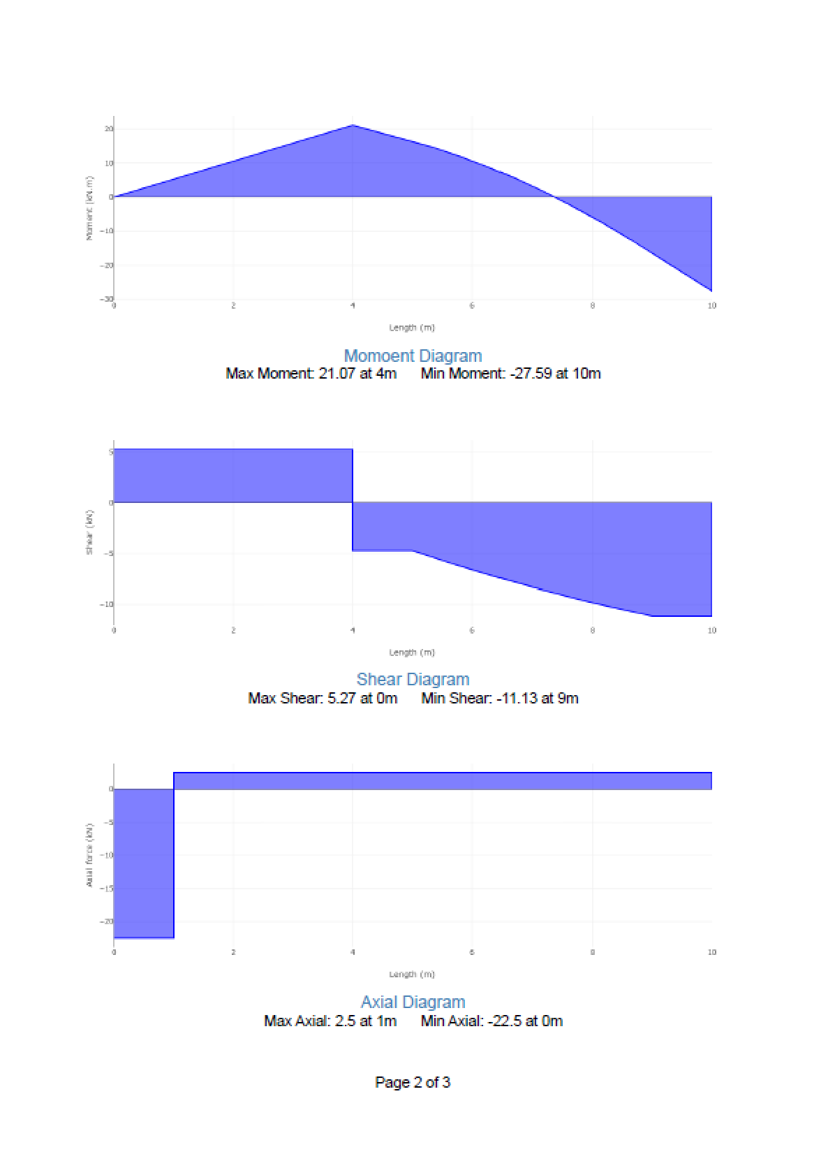
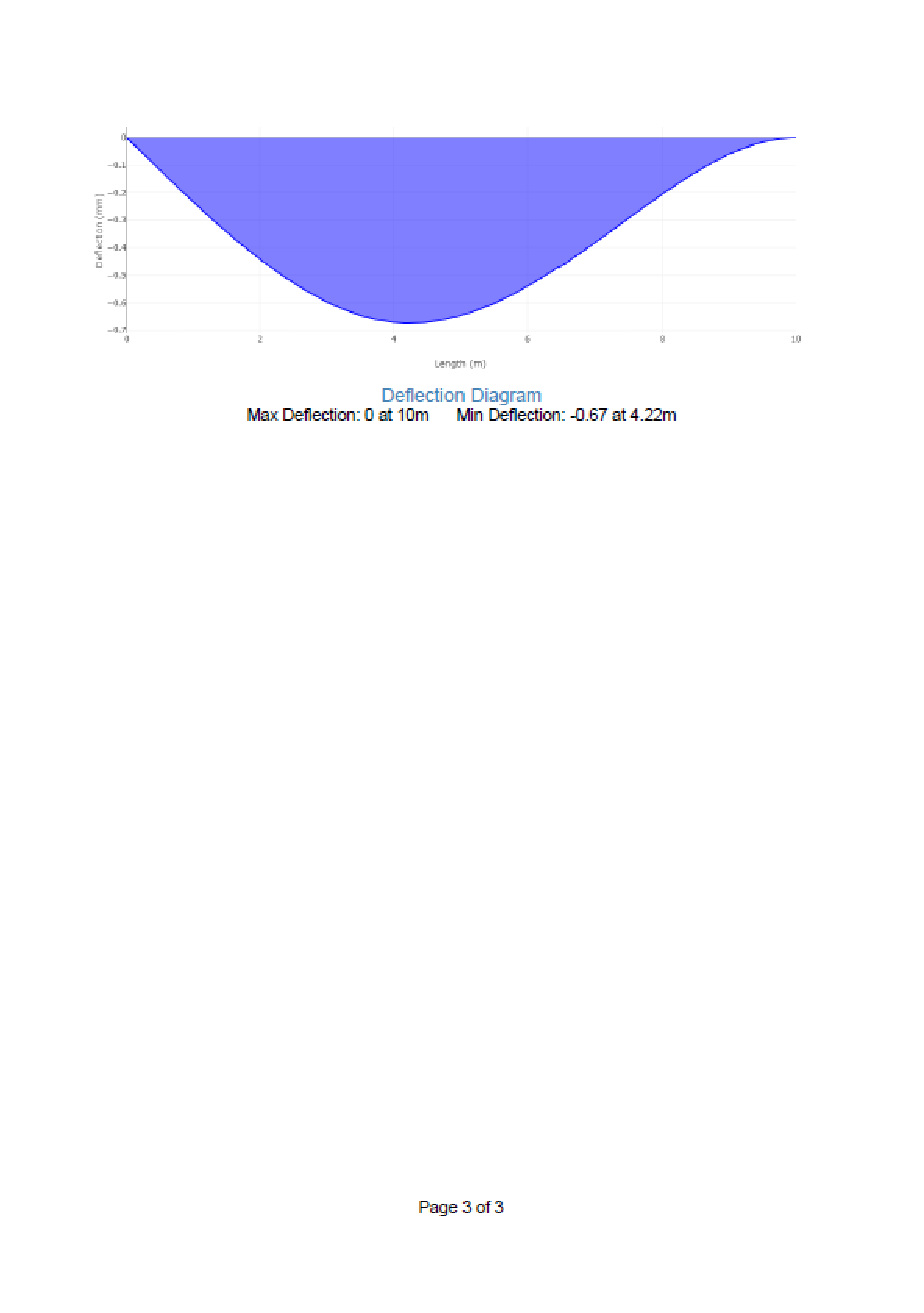
Calculation Results
- Reactions: Support forces and moments calculated automatically
- Diagrams: Shear, moment, axial, and deflection plots with max/min values
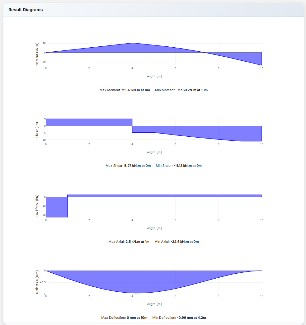
PDF Export
Generate a visual report including diagrams, tables, and calculations.
Error Handling: Alerts display if the model is unstable or loads are invalid.
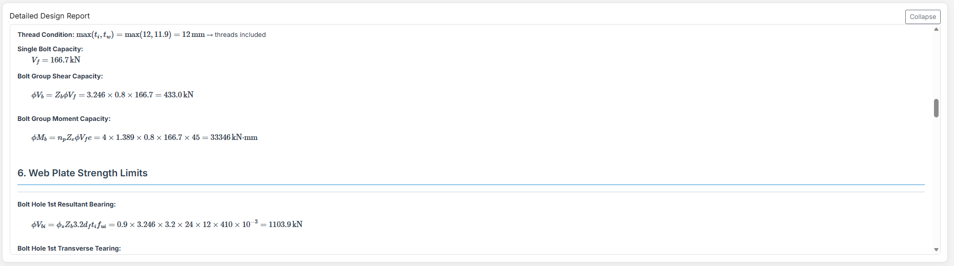
Web Side Plates Connection
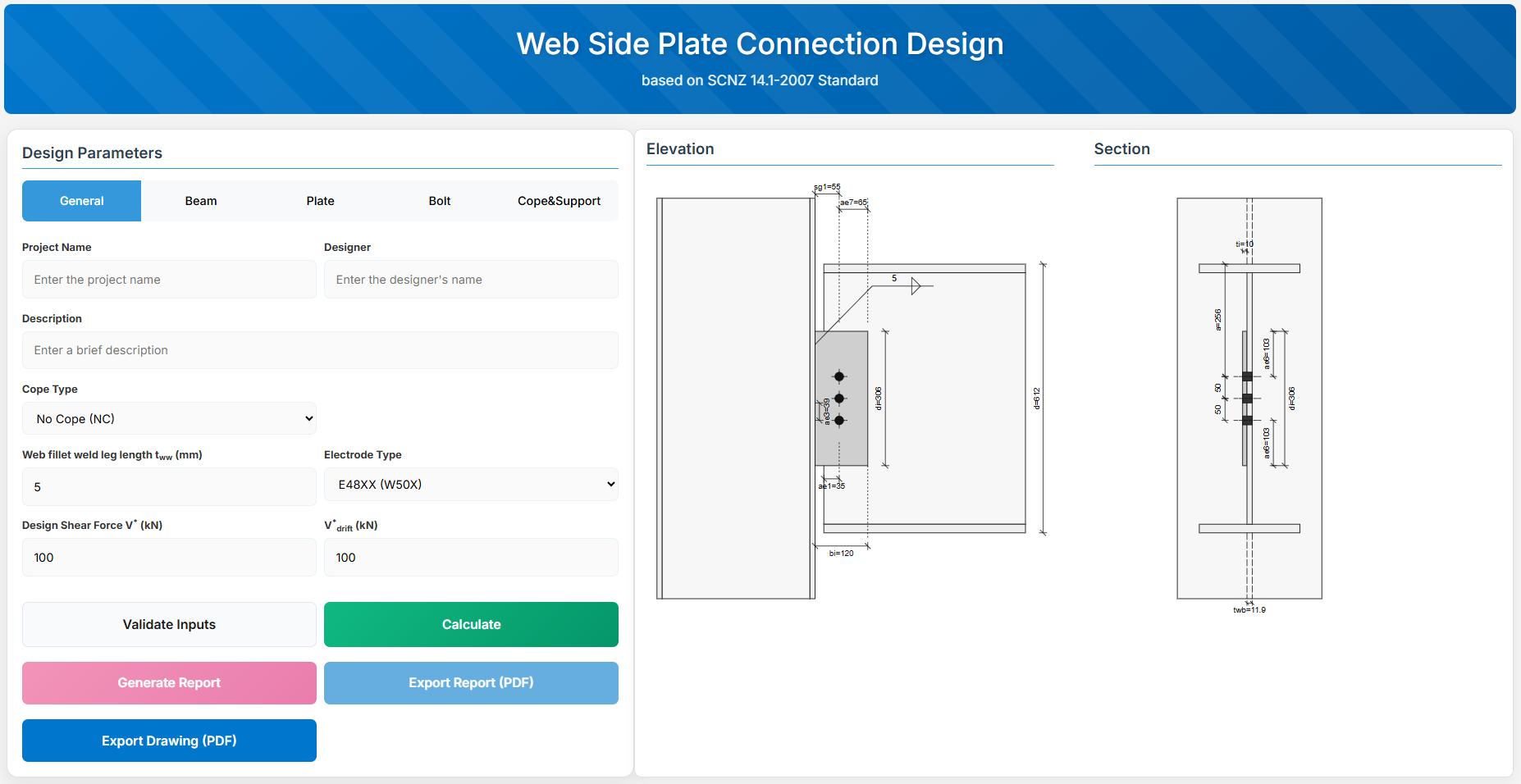
1. Overview
Web Side Plate Connection Design module provides a comprehensive approach for designing bolt sizes, web plates, and welds in accordance with SCNZ 14.1-2007 Standard.
 ↑ Back to Top
2. General Setup
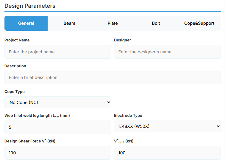
Project Information
This section captures essential metadata that will appear in your final design documentation.
- Project Name: Enter the name of the project. This helps identify the design file and appears in reports.
- Designer: The name of the person responsible for the connection design.
- Description: A brief overview of the connection design purpose or scope.
Connection Configuration - Cope Type Selection
Select the appropriate cope type based on your design requirements and beam end conditions. Different cope types affect the limiting design conditions:
-
NC (No Cope): Standard connection with no cope at beam end. Beam section remains intact.
-
SWC (Single Web Cope): Single web cope on one flange side. Reduces section depth on one side.
-
DWC (Double Web Cope): Double web cope on both flange sides. Reduces section depth on both sides symmetrically.
Weld Configuration
Define the fillet weld parameters for connecting the web plate to the support.
-
Web Fillet Weld Leg Length (tww): Specify the fillet weld size in millimeters
-
Electrode Type:
- E41XX (W40X): 410 MPa yield strength
- E48XX (W50X): 490 MPa yield strength
Loading Parameters
-
Design Shear Force (V*): The primary design shear force in kN
-
Seismic Shear Force (V*drift): Seismic drift-induced shear force in kN
- Required for seismic design verification of rotation capacity and end gap adequacy
↑ Back to Top
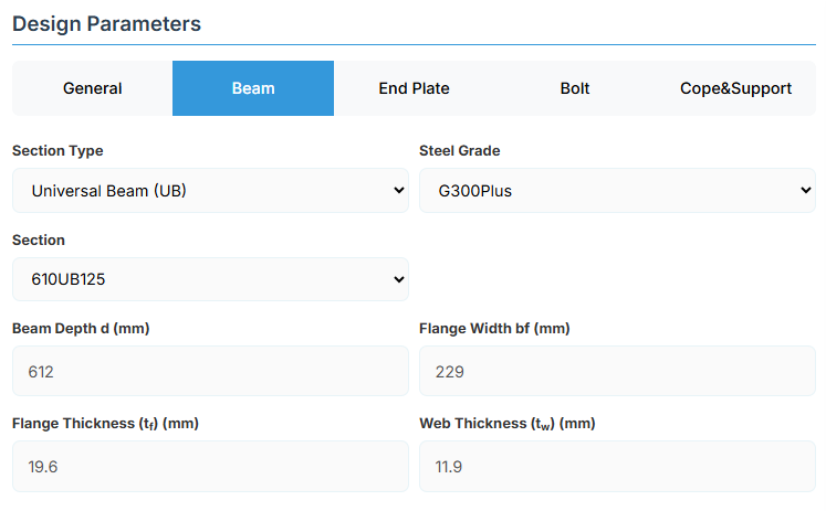
3. Beam Properties

Section Type:
The application provides a comprehensive library of Australian and New Zealand standard sections. Per SCNZ 14.1, design strength limits vary based on section type (HR vs Welded). Section properties are automatically calculated from standard tables or user inputs.
- UB (Universal Beam) - Grades G350 and G300+
- UC (Universal Column) - Grades G350 and G300+
-
CWB (Custom Welded Beam) - Various grades.
- TFB (Tapered Flange Beam) - Grades G350 and G300+
- PB (Perimeter Welded Beams) - Grade G300M
- EB (Equivalent Welded Beams) - Grade G300M
- HB (Heavy Welded Beams) - Grade G300M
- HCB (High Capacity Beams) - Grade G300M
- HCBC (High Capacity Beam-Columns) - Grade G300M
- HCC (High Capacity Columns) - Grade G300M
- HP (Welded 'H' Piles) - Grade G300M
- NB (Narrow Welded Beams) - Grade G300M
- BP (Welded Bearing Piles) - Grade G300M
- SB (Standard Welded Beams) - Grade G300M
- SC (Standard Welded Columns) - Grade G300M
- LB (Light Welded Beams) - Grade G300M
- WS (Wide Sections) - Grade G300M
Section: Automatically populated based on the selected section type. The user can then select a specific section from the list.
When CWB is selected, manual inputs for depth (d), flange width (bf), flange thickness (tf), and web thickness (tw) become available.
↑ Back to Top
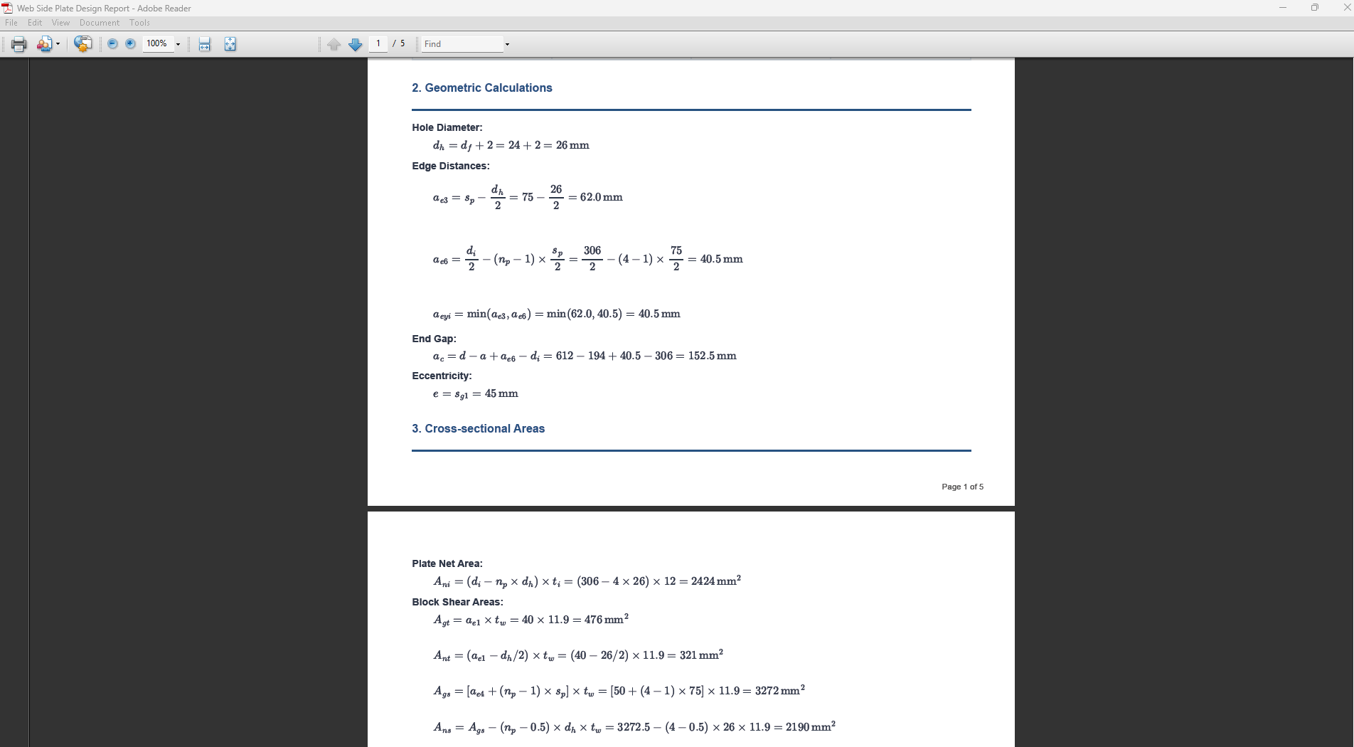
4. Plate Details

Plate Material
Select the steel grade for the web side plate. Plate material properties (fyi and fui) are used in design calculations.
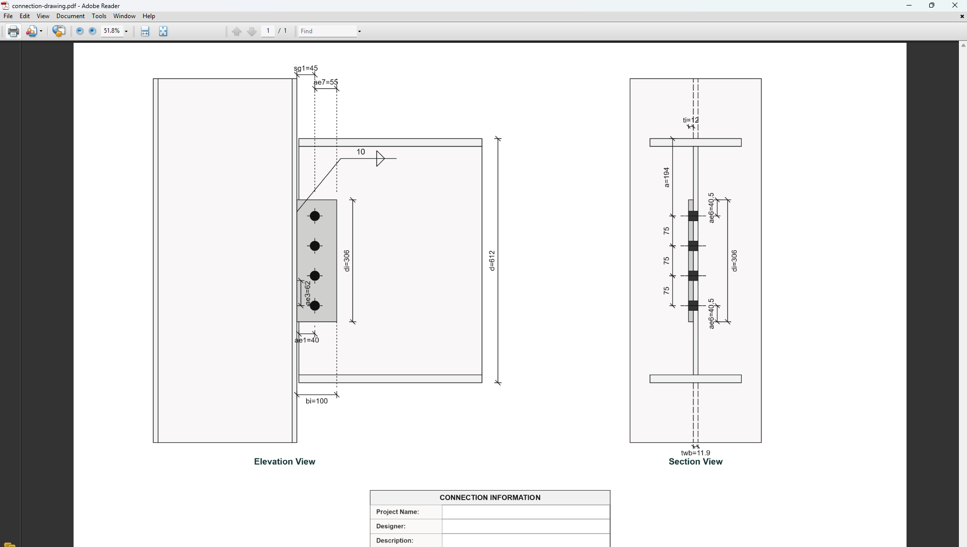
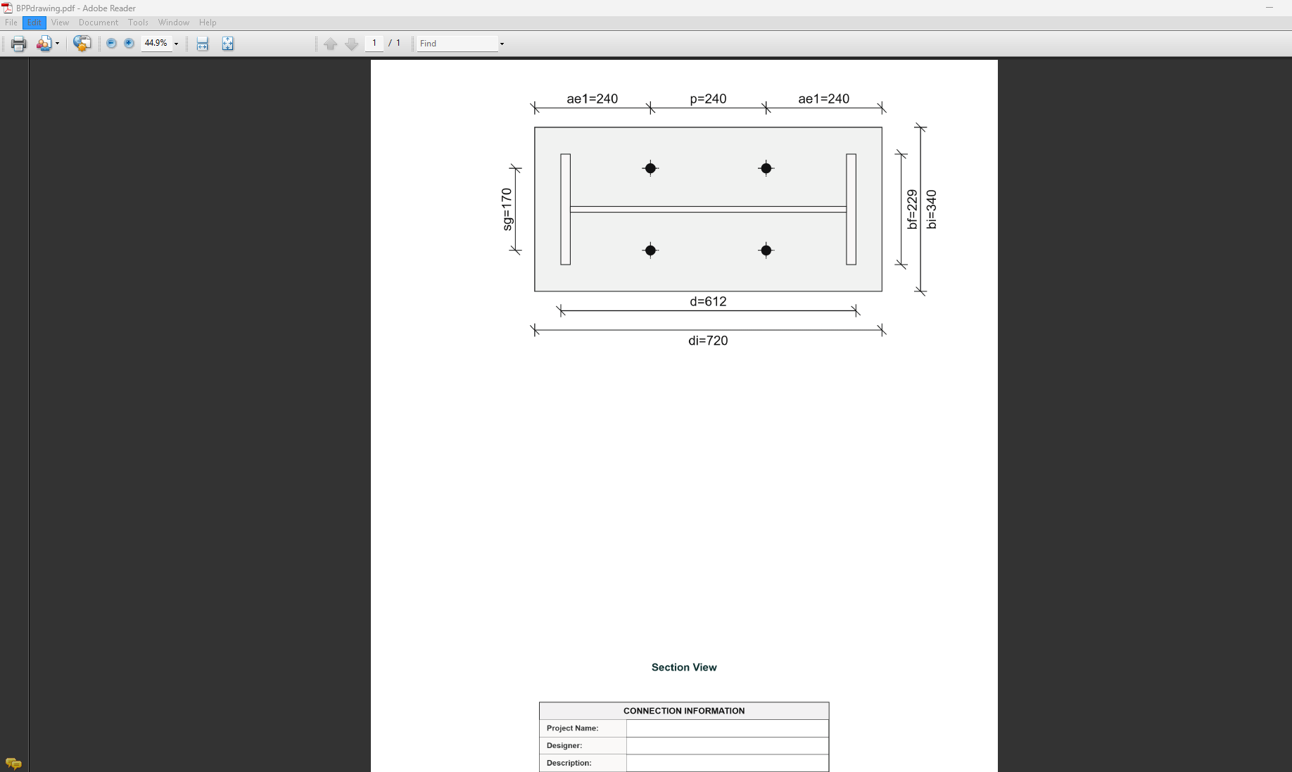
Plate Geometry
Define the dimensions of the web side plate. These parameters directly affect the connection's load-carrying capacity.
-
Plate Depth (di): Height of the plate in mm
-
Plate Width (bi): Width of the plate in mm
-
Plate Thickness (ti):Thickness of the plate in mm
↑ Back to Top
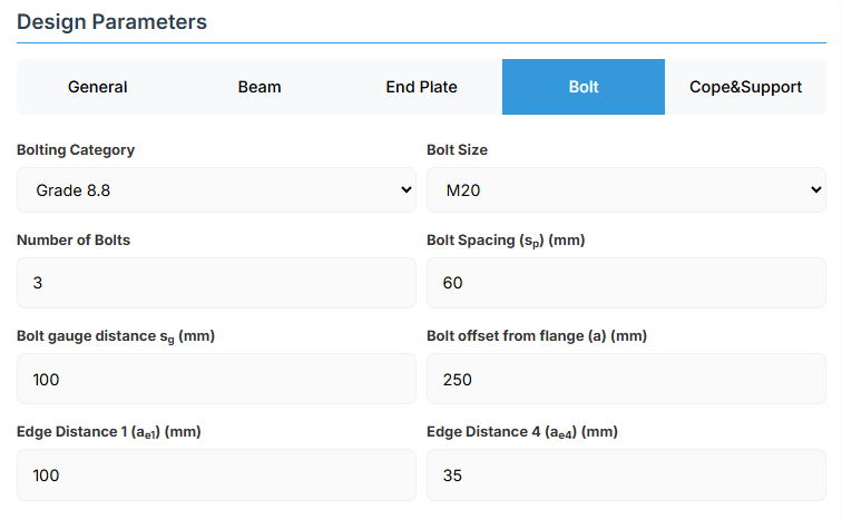
5. Bolt Configuration
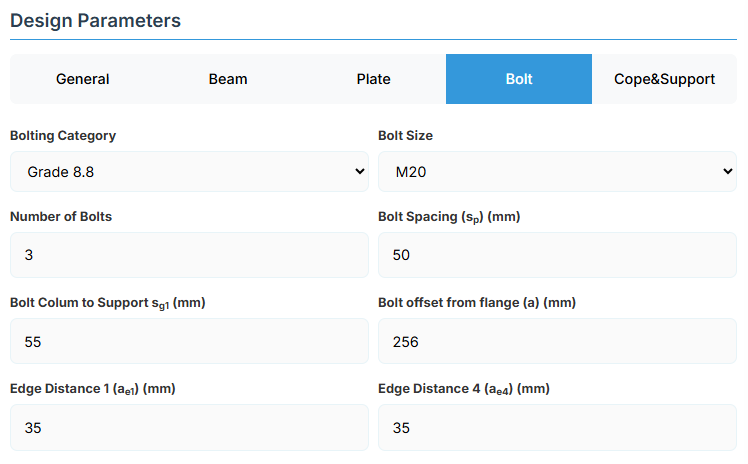
Bolt Category and Size
- Bolting Category: Class 8.8 - High-strength bolts with 830 MPa tensile strength
-
Bolt Size:
Bolt Group Configuration
-
Number of Bolts: Total number of bolts in the connection
-
Bolt Spacing (sp): Distance between bolt centerlines
Bolt Position Parameters
-
Bolt Column to Support (sg1): Distance from first bolt column to support edge
-
Bolt Offset from Flange (a): Distance from beam flange to nearest bolt hole
Edge Distances
-
Edge Distance 1 (ae1): Distance from bolt hole to the beam end
-
Edge Distance 4 (ae4): Distance from cope to nearest bolt hole
↑ Back to Top
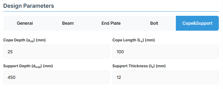
6. Cope & Support
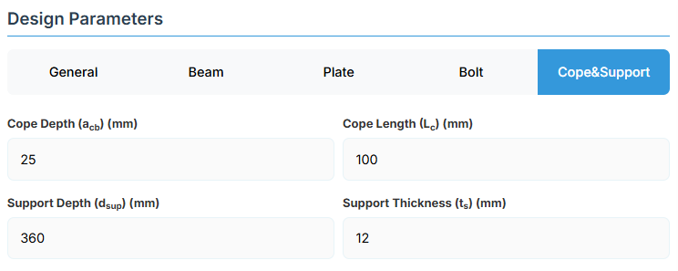
Cope Configuration
Define the cope geometry at the beam end. The cope provides clearance for connection assembly and beam rotation.
-
Cope Depth (acb): Vertical depth of the cope
-
Cope Length (Lc): Horizontal length of the cope
Support Member Details
-
Support Depth (dsup): Total depth of the support member
-
Support Thickness (ts): Edge thickness of the support member
↑ Back to Top
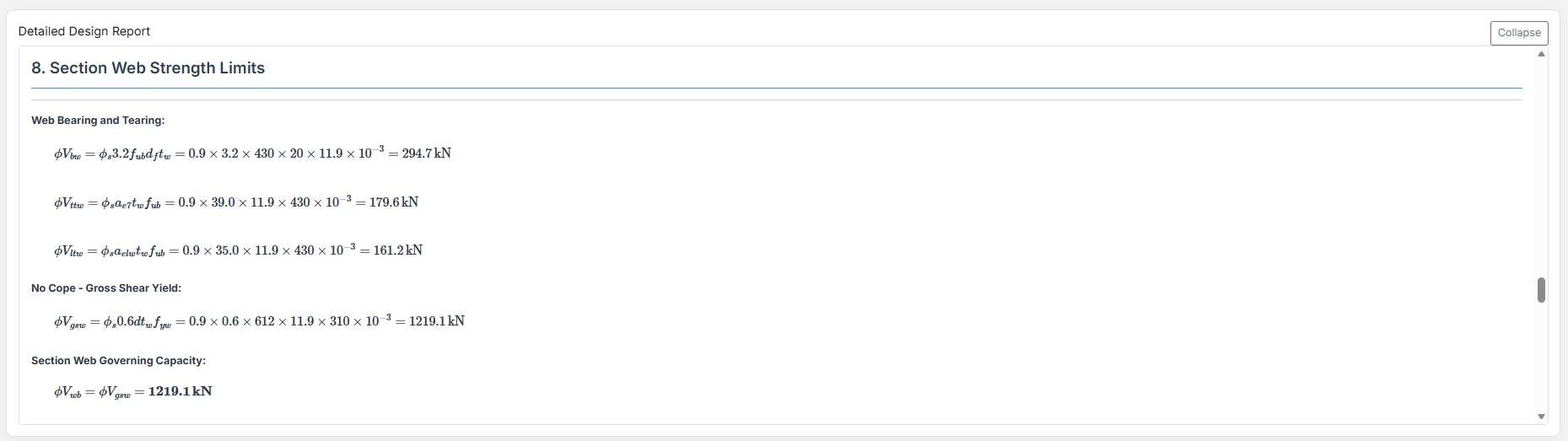
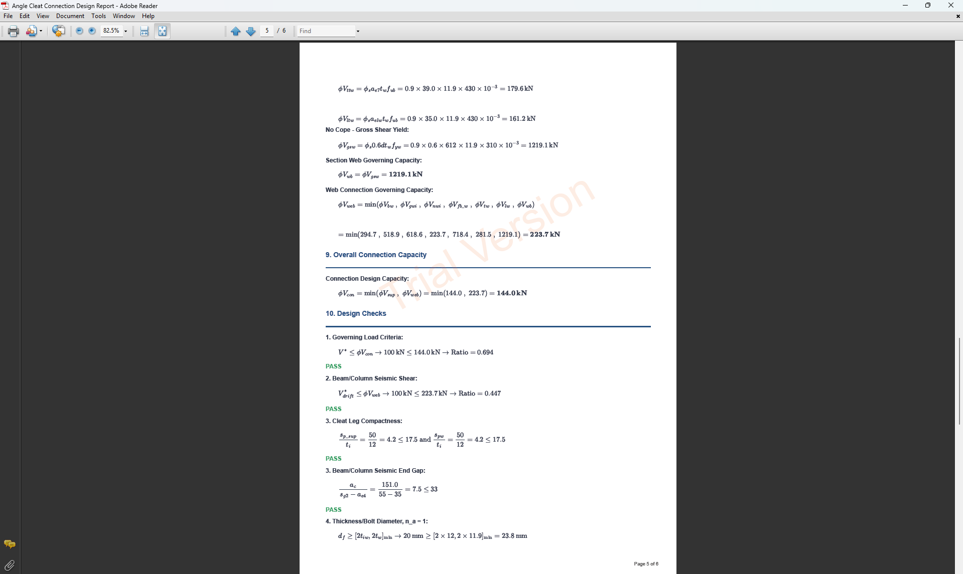
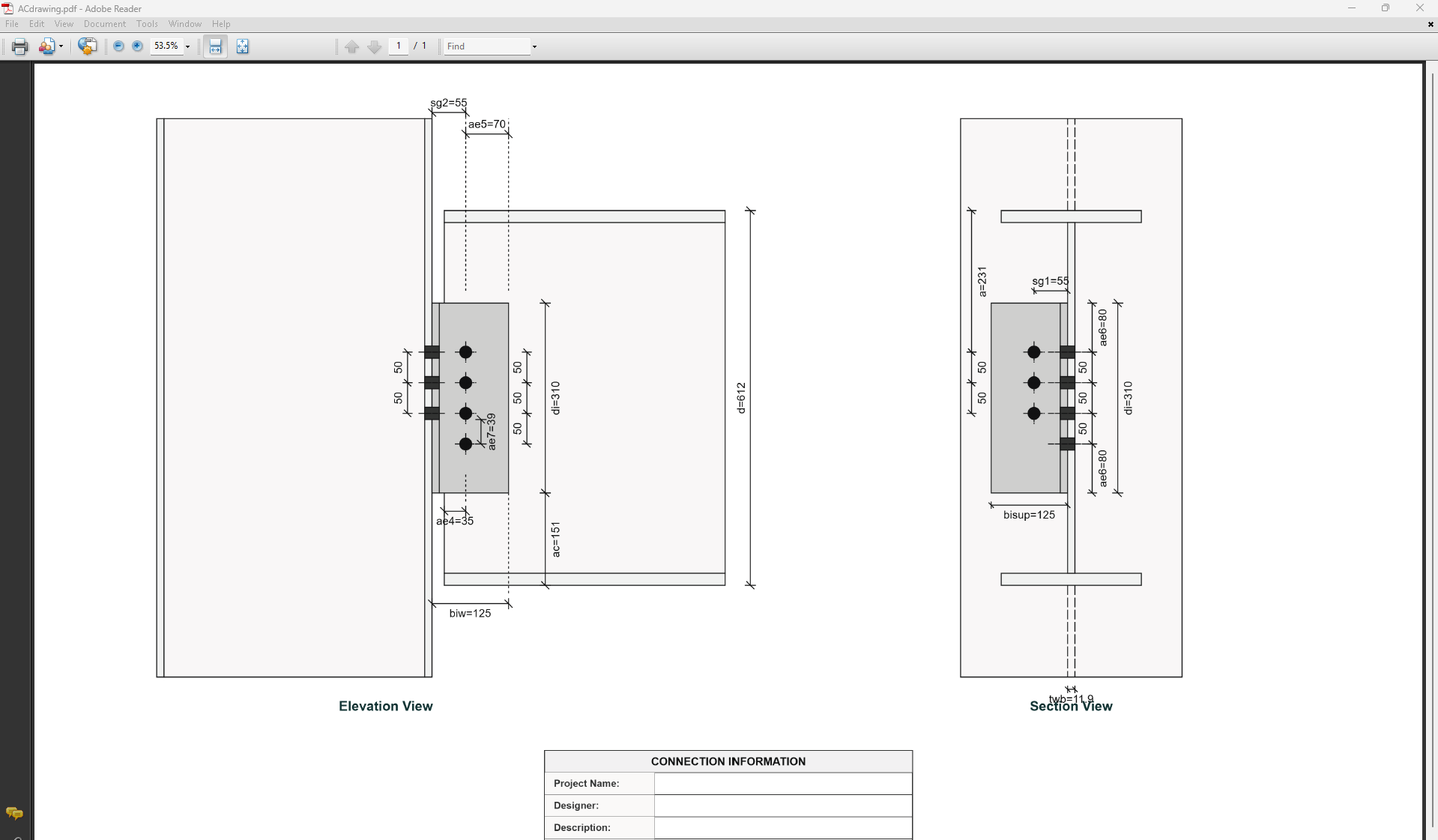
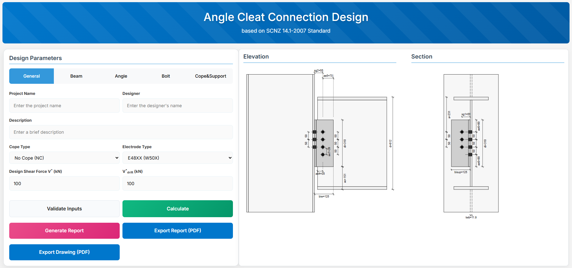
Angle Cleat Connection Design
1. Overview
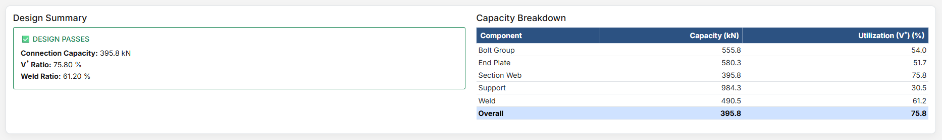
The Angle Cleat Connection Design module provides a comprehensive tool for designing bolted angle cleat connections in accordance with SCNZ 14.1-2007 Standard. It checks bolts, angles, beam web, and supporting member under applied shear forces.
 ↑ Back to Top
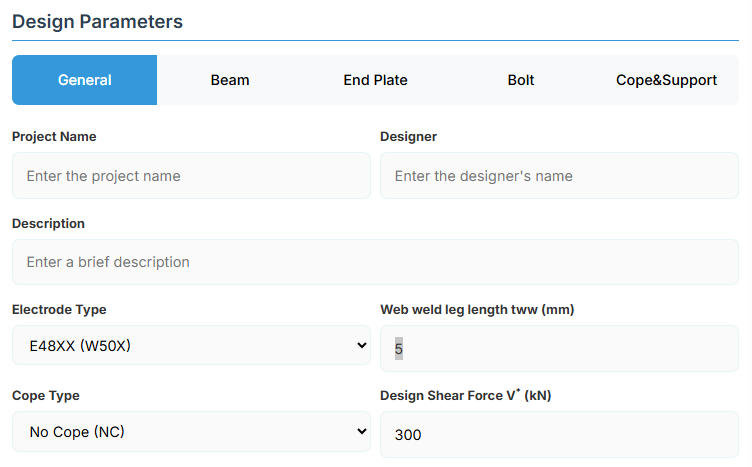
2. General Setup
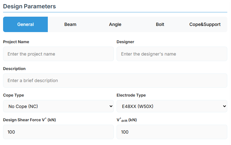
Project Information
This section captures metadata that will be included in the final design report.
- Project Name: Name of the project for identification and reporting.
- Designer: Name of the engineer responsible for the design.
- Description: Brief description of the connection or its application.
Connection Configuration
-
Cope Type: Select the beam end condition:
- No Cope (NC): Full beam section at connection (default).
- Single Web Cope (SWC): Cope applied to one flange.
- Double Web Cope (DWC): Cope applied to both flanges.
-
Electrode Type: Weld electrode strength (used for any supplementary welds if required):
- E41XX (W40X): 410 MPa class.
- E48XX (W50X): 490 MPa class (default).
Loading Parameters
- Design Shear Force V* (kN): Primary vertical shear force acting on the connection.
- V*drift (kN): Additional shear force induced by seismic drift (used for rotation capacity and gap checks).
↑ Back to Top
3. Beam Properties
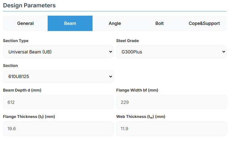
Section Type:
The application provides a comprehensive library of Australian and New Zealand standard sections. Per SCNZ 14.1, design strength limits vary based on section type (HR vs Welded). Section properties are automatically calculated from standard tables or user inputs.
- UB (Universal Beam) - Grades G350 and G300+
- UC (Universal Column) - Grades G350 and G300+
-
CWB (Custom Welded Beam) - Various grades.
- TFB (Tapered Flange Beam) - Grades G350 and G300+
- PB (Perimeter Welded Beams) - Grade G300M
- EB (Equivalent Welded Beams) - Grade G300M
- HB (Heavy Welded Beams) - Grade G300M
- HCB (High Capacity Beams) - Grade G300M
- HCBC (High Capacity Beam-Columns) - Grade G300M
- HCC (High Capacity Columns) - Grade G300M
- HP (Welded 'H' Piles) - Grade G300M
- NB (Narrow Welded Beams) - Grade G300M
- BP (Welded Bearing Piles) - Grade G300M
- SB (Standard Welded Beams) - Grade G300M
- SC (Standard Welded Columns) - Grade G300M
- LB (Light Welded Beams) - Grade G300M
- WS (Wide Sections) - Grade G300M
Section: Automatically populated based on the selected section type. The user can then select a specific section from the list.
When CWB is selected, manual inputs for depth (d), flange width (bf), flange thickness (tf), and web thickness (tw) become available.
↑ Back to Top
4. Angle Cleat Details
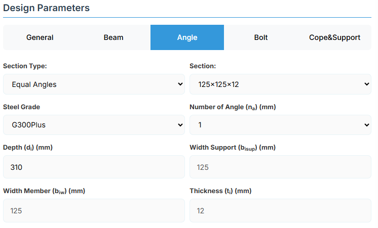
Angle Section
-
Section Type:
- EA – Equal Angles
- UA – Unequal Angles
- Section: Specific angle designation from the standard library.
- Steel Grade: G250, G300, G350, or G450.
- Number of Angles (na): 1 (single cleat) or 2 (double cleat, one each side of web).
Manual Angle Dimensions (override library)
If a non-standard angle is required, the following dimensions can be entered manually:
- Depth (di): Overall leg length along the beam depth (mm).
- Width Support (bisup): Outstanding leg length attached to support (mm).
- Width Member (biw): Outstanding leg length attached to beam web (mm).
- Thickness (ti): Angle thickness (mm).
↑ Back to Top
5. Bolt Configuration
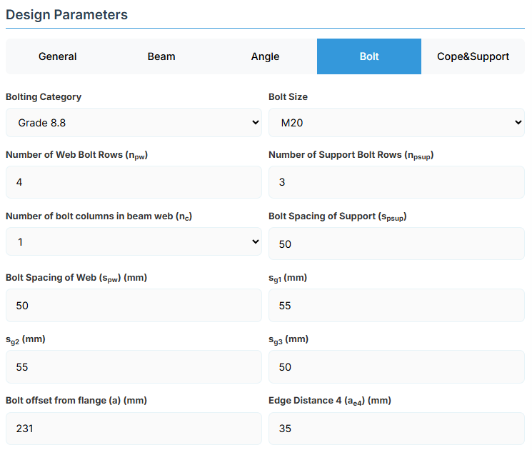
Bolt Properties
- Bolting Category: Class 8.8 - High-strength bolts with 830 MPa tensile strength
-
Bolt Size:
Bolt Layout
- Number of Web Bolt Rows (npw): Bolts along beam depth on member side.
- Number of Support Bolt Rows (npsup): Bolts along depth on support side.
- Number of Bolt Columns in Beam Web (nc): 1 or 2 columns.
- Bolt Spacing of Support (spsup): Vertical gauge on support leg (mm).
- Bolt Spacing of Web (spw): Vertical gauge on member leg (mm).
Gauge and Edge Distances
- sg1, sg2, sg3 (mm): Horizontal gauges defining bolt positions.
- Bolt Offset from Flange (a): Distance from beam top flange to the top bolt row (mm).
- Edge Distance 4 (ae4): Bolt side edge distance (mm).
↑ Back to Top
6. Cope & Support
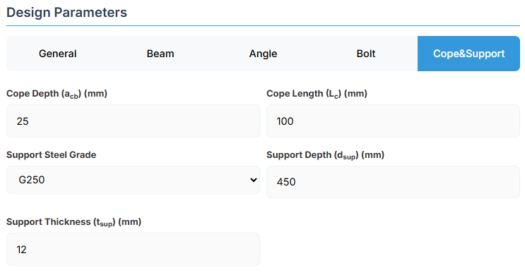
Cope Geometry
- Cope Depth (acb): Vertical depth of flange/web removal at beam end (mm).
- Cope Length (Lc): Horizontal length of the cope (mm).
Supporting Member
- Support Steel Grade: G250, G300, G300M, G300Plus, G350, or G450.
- Support Depth (dsup): Depth of the supporting member (mm).
- Support Thickness (tsup): Thickness of the supporting element (e.g., column flange or beam web) (mm).
↑ Back to Top
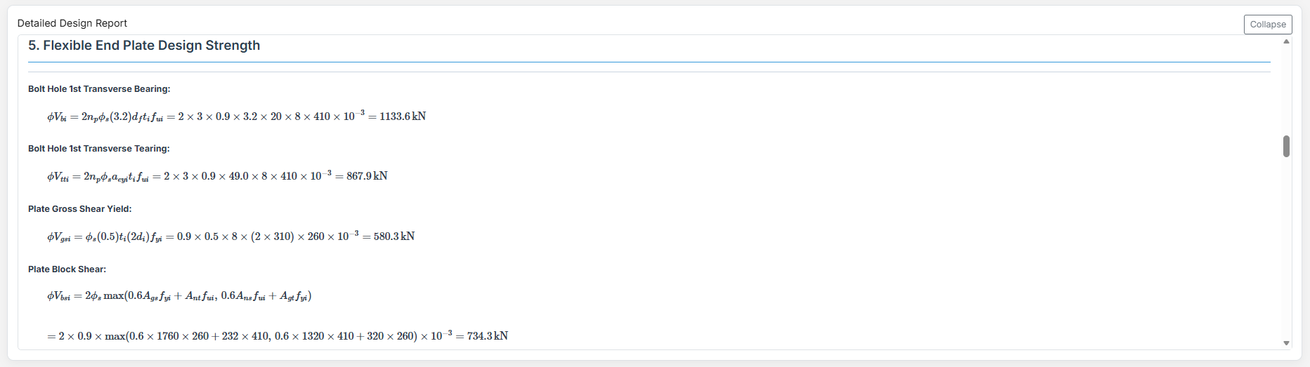
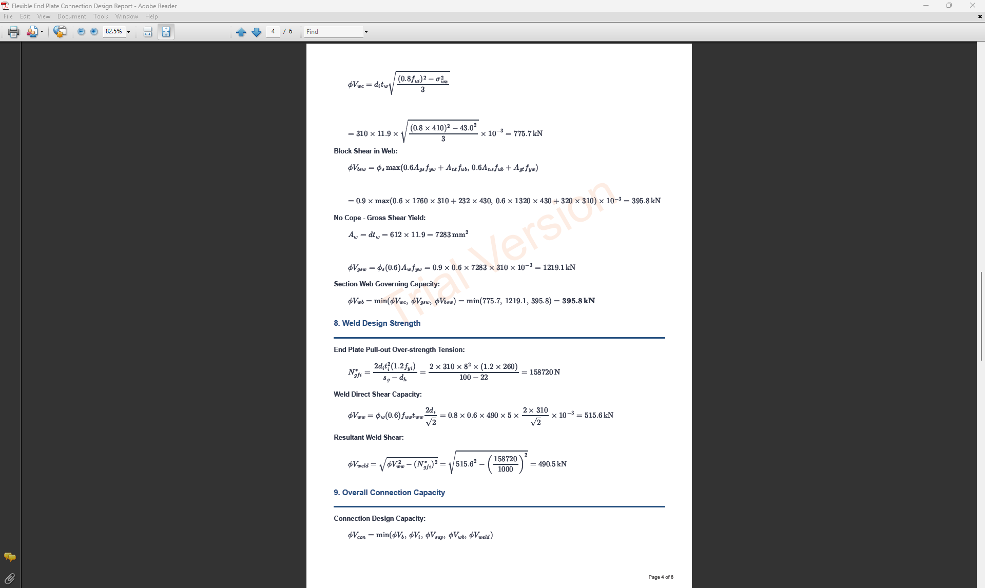
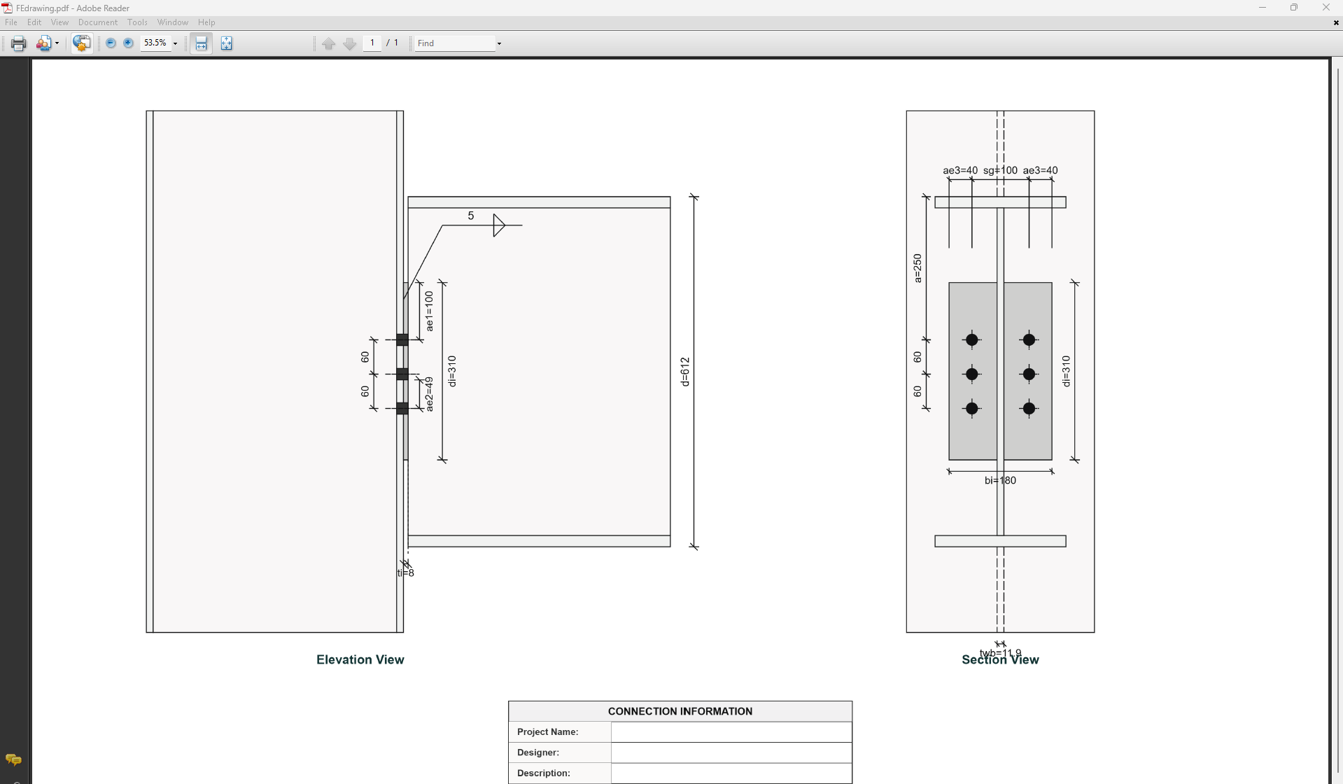
Flexible End Plate Connection
1. Overview
The Flexible End Plate Connection Design module provides a comprehensive approach for designing flexible end plate connections in accordance with SCNZ 14.1-2007 Standard. The connection is designed to satisfy gravity ultimate limit state loads, provide twist restraint, accommodate rotations up to 0.030 radians under seismic drift, and handle thermal strains from fire events without collapse.
 ↑ Back to Top
2. General Setup
Project Information
This section captures essential metadata that will appear in your final design documentation.
- Project Name: Enter the name of the project. This helps identify the design file and appears in reports.
- Designer: The name of the person responsible for the connection design.
- Description: A brief overview of the connection design purpose or scope.
Connection Configuration - Cope Type Selection
Select the appropriate cope type based on your design requirements and beam end conditions. Different cope types affect the limiting design conditions:
- NC (No Cope): Standard connection with no cope at beam end. Beam section remains intact.
- SWC (Single Web Cope): Single web cope on one flange side. Reduces section depth on one side.
- DWC (Double Web Cope): Double web cope on both flange sides. Reduces section depth on both sides symmetrically.
Weld Configuration
Define the fillet weld parameters for connecting the end plate to the beam web.
- Web Fillet Weld Leg Length (tww): Specify the fillet weld size in millimeters.
-
Electrode Type:
- E41XX (W40X): 410 MPa yield strength.
- E48XX (W50X): 490 MPa yield strength.
Loading Parameters
- Design Shear Force (V*): The primary design shear force in kN.
↑ Back to Top
3. Beam Properties
Section Type:
The application provides a comprehensive library of Australian and New Zealand standard sections. Per SCNZ 14.1, design strength limits vary based on section type (HR vs Welded). Section properties are automatically calculated from standard tables or user inputs.
- UB (Universal Beam) - Grades G350 and G300+
- UC (Universal Column) - Grades G350 and G300+
-
CWB (Custom Welded Beam) - Various grades.
- TFB (Tapered Flange Beam) - Grades G350 and G300+
- PB (Perimeter Welded Beams) - Grade G300M
- EB (Equivalent Welded Beams) - Grade G300M
- HB (Heavy Welded Beams) - Grade G300M
- HCB (High Capacity Beams) - Grade G300M
- HCBC (High Capacity Beam-Columns) - Grade G300M
- HCC (High Capacity Columns) - Grade G300M
- HP (Welded 'H' Piles) - Grade G300M
- NB (Narrow Welded Beams) - Grade G300M
- BP (Welded Bearing Piles) - Grade G300M
- SB (Standard Welded Beams) - Grade G300M
- SC (Standard Welded Columns) - Grade G300M
- LB (Light Welded Beams) - Grade G300M
- WS (Wide Sections) - Grade G300M
Section: Automatically populated based on the selected section type. The user can then select a specific section from the list.
When CWB is selected, manual inputs for depth (d), flange width (bf), flange thickness (tf), and web thickness (tw) become available.
↑ Back to Top
4. End Plate Details
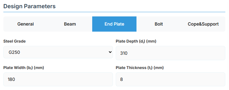
Plate Material
Select the steel grade for the end plate. Plate material properties (fyi and fui) are used in design calculations.
Plate Geometry
Define the dimensions of the end plate. These parameters directly affect the connection's load-carrying capacity and flexibility.
- Plate Depth (di): Height of the plate in mm.
- Plate Width (bi): Width of the plate in mm.
- Plate Thickness (ti): Thickness of the plate in mm. Limited to maintain flexibility as per bolt gauge.
↑ Back to Top
5. Bolt Configuration
Bolt Category and Size
- Bolting Category: Class 8.8 - High-strength bolts with 830 MPa tensile strength.
-
Bolt Size:
Bolt Group Configuration
- Number of Bolts: Total number of bolts in the connection (minimum 2).
- Bolt Spacing (sp): Distance between bolt centerlines.
- Bolt Gauge Distance (sg): Lateral spacing between bolt columns.
- Bolt Offset from Flange (a): Distance from beam flange to nearest bolt hole.
Edge Distances
- Edge Distance 1 (ae1): Distance from bolt hole to the beam end.
- Edge Distance 4 (ae4): Distance from cope to nearest bolt hole.
↑ Back to Top
6. Cope & Support
Cope Configuration
Define the cope geometry at the beam end. The cope provides clearance for connection assembly and beam rotation.
- Cope Depth (acb): Vertical depth of the cope.
- Cope Length (Lc): Horizontal length of the cope.
Support Member Details
- Support Depth (dsup): Total depth of the support member.
- Support Thickness (ts): Edge thickness of the support member.
↑ Back to Top
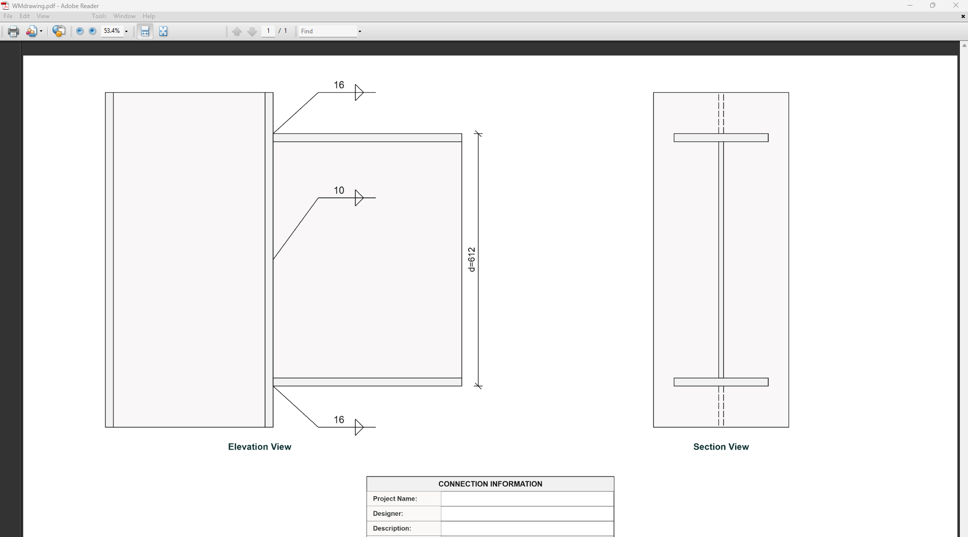
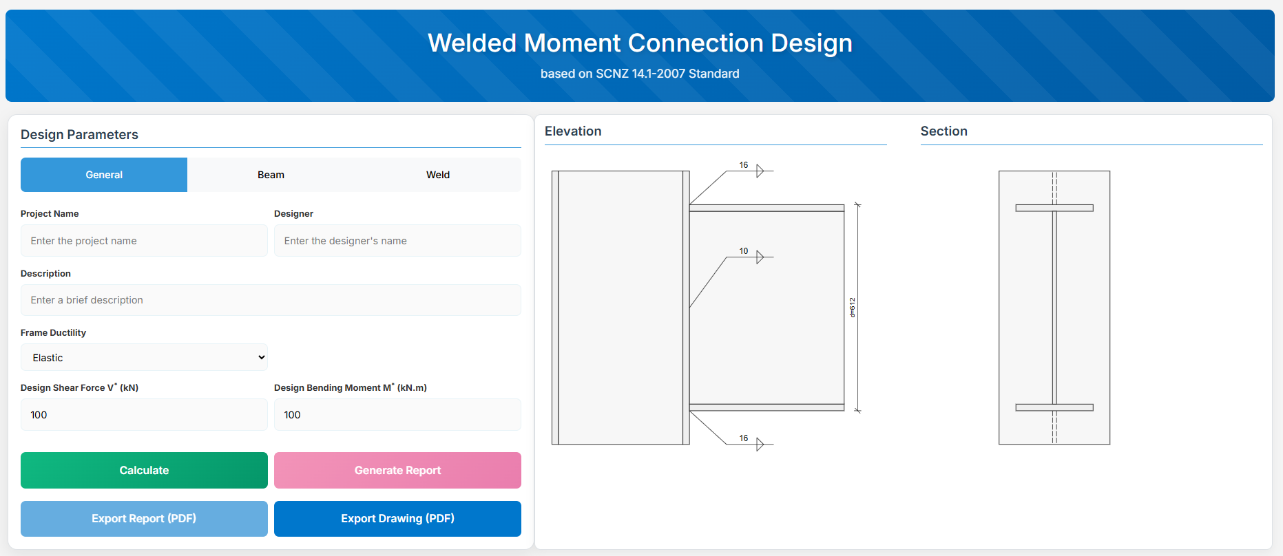
Welded Moment Connection
1. Overview
The Welded Moment Connection Design module provides a comprehensive approach for designing a beam to column face welded connection in accordance with SCNZ 14.1-2007 Standard. It is designed to satisfy the demands of primary members in frames of varying seismic ductility categories, including ductile frames (μ > 3), limited ductile frames (1.25 ≤ μ ≤ 3), and elastic frames (μ ≤ 1.25).
Note: Compression and tension stiffeners and column web doubler plate are not specified but may be required to develop the design reactions from the connection.
 ↑ Back to Top
2. General Setup
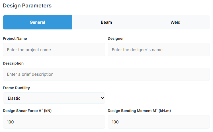
Project Information
This section captures essential metadata that will appear in your final design documentation.
- Project Name: Enter the name of the project. This helps identify the design file and appears in reports.
- Designer: The name of the person responsible for the connection design.
- Description: A brief overview of the connection design purpose or scope.
Frame Configuration
-
Frame Ductility: Select the seismic ductility category of the frame:
- Elastic: μ ≤ 1.25 (default).
- Limited Ductile: 1.25 ≤ μ ≤ 3.
- Ductile: μ > 3.
Loading Parameters
- Design Shear Force (V*): The primary design shear force in kN.
- Design Bending Moment (M*): The primary design bending moment in kN.m.
↑ Back to Top
3. Beam Properties
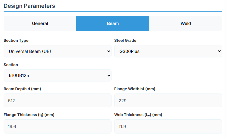
Section Type:
The application provides a comprehensive library of Australian and New Zealand standard sections. Per SCNZ 14.1, design strength limits vary based on section type (HR vs Welded). Section properties are automatically calculated from standard tables or user inputs. Sections must satisfy the material and section geometry requirements of NZS3404:1997 Sections 12.4 and 12.5, appropriate to the seismic ductility demand category of the frame.
- UB (Universal Beam) - Grades G350 and G300+
- UC (Universal Column) - Grades G350 and G300+
-
CWB (Custom Welded Beam) - Various grades.
- TFB (Tapered Flange Beam) - Grades G350 and G300+
- PB (Perimeter Welded Beams) - Grade G300M
- EB (Equivalent Welded Beams) - Grade G300M
- HB (Heavy Welded Beams) - Grade G300M
- HCB (High Capacity Beams) - Grade G300M
- HCBC (High Capacity Beam-Columns) - Grade G300M
- HCC (High Capacity Columns) - Grade G300M
- HP (Welded 'H' Piles) - Grade G300M
- NB (Narrow Welded Beams) - Grade G300M
- BP (Welded Bearing Piles) - Grade G300M
- SB (Standard Welded Beams) - Grade G300M
- SC (Standard Welded Columns) - Grade G300M
- LB (Light Welded Beams) - Grade G300M
- WS (Wide Sections) - Grade G300M
Section: Automatically populated based on the selected section type. The user can then select a specific section from the list.
When CWB is selected, manual inputs for depth (d), flange width (bf), flange thickness (tf), and web thickness (tw) become available.
↑ Back to Top
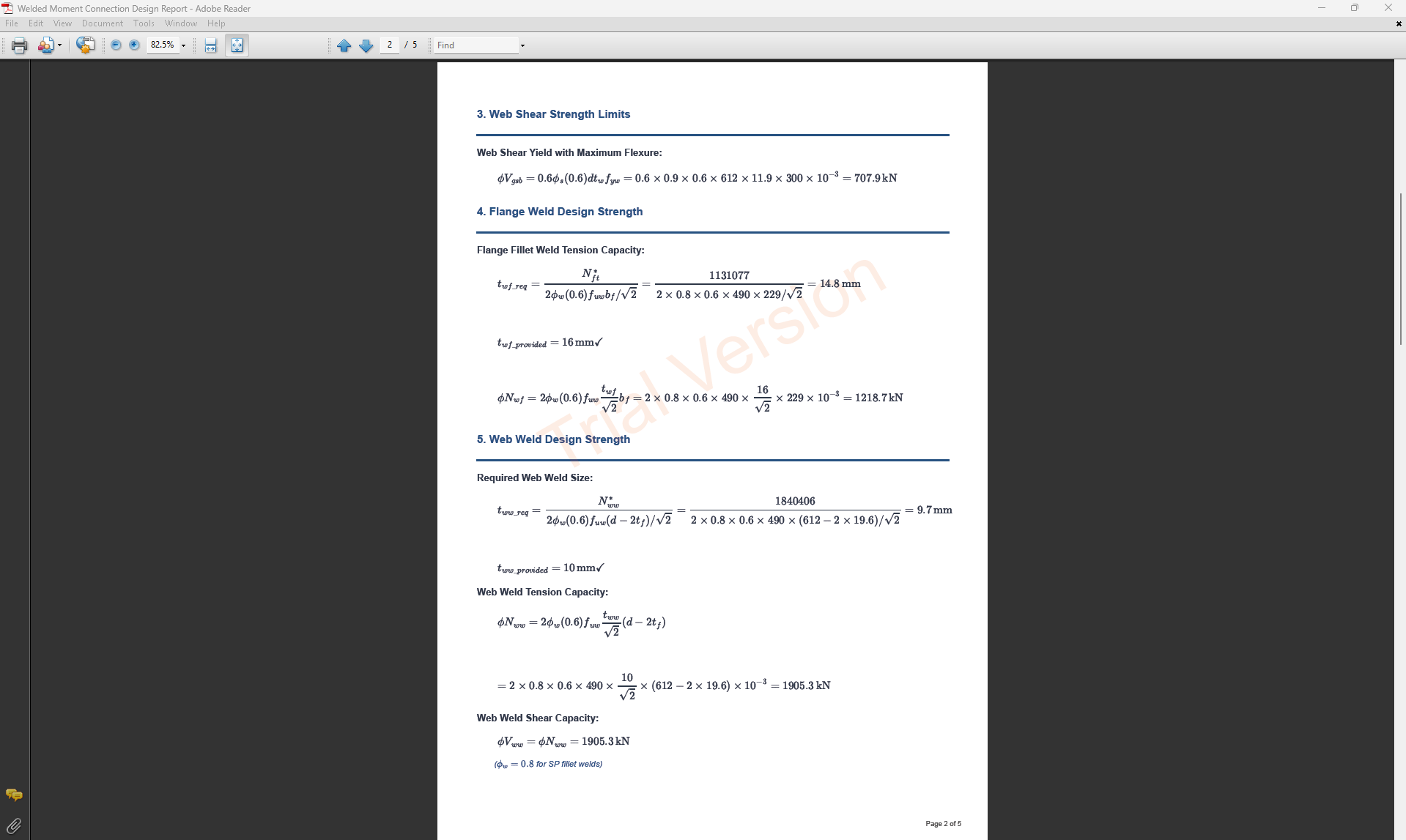
4. Weld Details
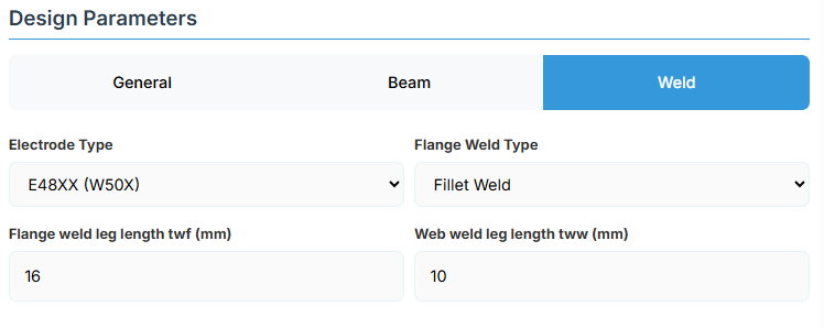
Weld Configuration
Define the weld parameters. The welds are sized to develop the design capacity of the web and flanges to enhance ductile behavior.
-
Electrode Type:
- E41XX (W40X): 410 MPa yield strength.
- E48XX (W50X): 490 MPa yield strength (default).
-
Flange Weld Type:
- Fillet Weld: Symmetrical fillet welds placed either side of the flanges (default). Designed to develop the corresponding over-strength design capacity of the flange based on the frame ductility.
- Complete Penetration Butt Weld: Suitable for all members in elastic, limited ductile, and ductile frames without specific design.
- Flange Weld Leg Length (twf): Size of the fillet weld on the flanges in mm (if Fillet Weld selected).
- Web Weld Leg Length (tww): Size of the fillet weld on the web in mm.
↑ Back to Top
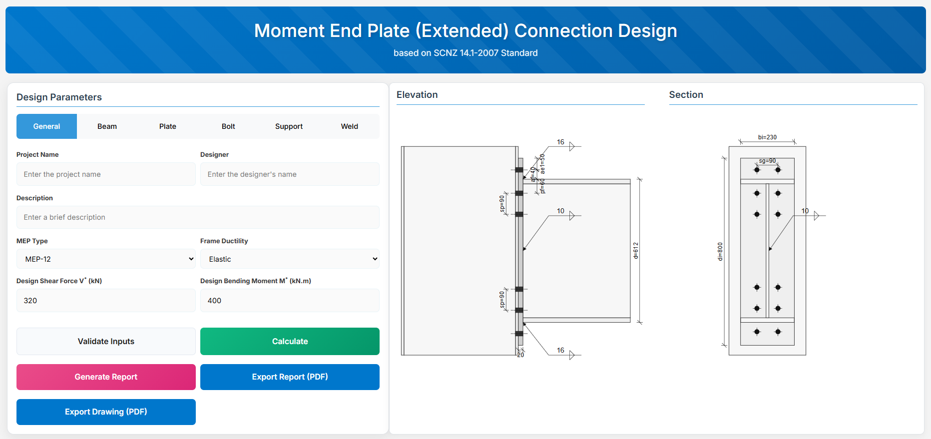
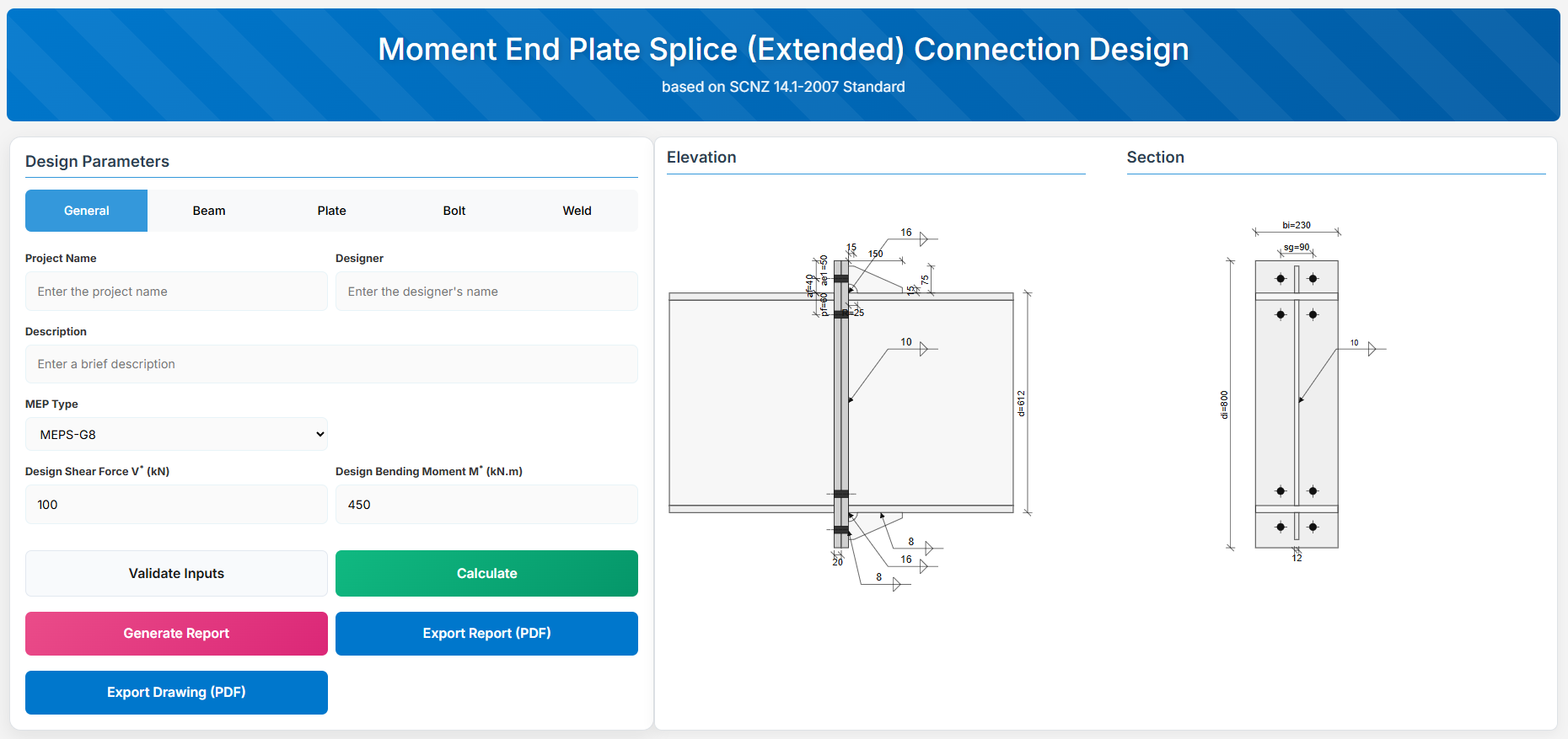
Moment End Plate (Extended) Connection
1. Overview
The Moment End Plate (Extended) Connection Design module provides a comprehensive approach for designing rigid beam-end connections for beam to column joints in accordance with SCNZ 14.1-2007 Standard.
The connections must possess design capacity to satisfy the flexural and shear ultimate limit state loads for primary members of limited ductile (1.25 ≤ μ ≤ 3) and elastic (μ ≤ 1.25) seismic ductility demand category frames.
Note: Compression and tension stiffeners and column web doubler plate are not specified but may be required to develop the design reactions from the connection.
 ↑ Back to Top
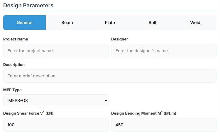
2. General Setup
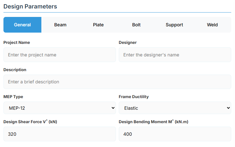
Project Information
This section captures essential metadata that will appear in your final design documentation.
- Project Name: Enter the name of the project. This helps identify the design file and appears in reports.
- Designer: The name of the person responsible for the connection design.
- Description: A brief overview of the connection design purpose or scope.
Connection Configuration
-
MEP Type: Select the type of moment end plate connection:
- MEP-8: 8-bolt configuration (default).
- MEP-G8: 8-bolt with gusset.
- MEP-10: 10-bolt configuration.
- MEP-G10: 10-bolt with gusset.
- MEP-12: 12-bolt configuration.
- MEP-G12: 12-bolt with gusset.
- STP-8: Steltech Portal Haunched Knee Joint.
-
Frame Ductility: Select the seismic ductility category of the frame:
- Elastic: μ ≤ 1.25 (default).
- Limited Ductile: 1.25 ≤ μ ≤ 3.
- Ductile: μ > 3.
Loading Parameters
- Design Shear Force (V*): The primary design shear force in kN.
- Design Bending Moment (M*): The primary design bending moment in kN.m.
↑ Back to Top
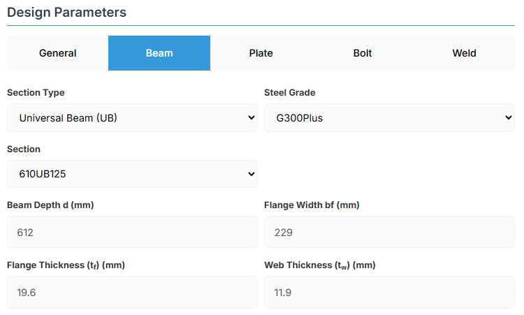
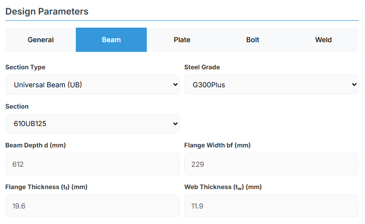
3. Beam Properties
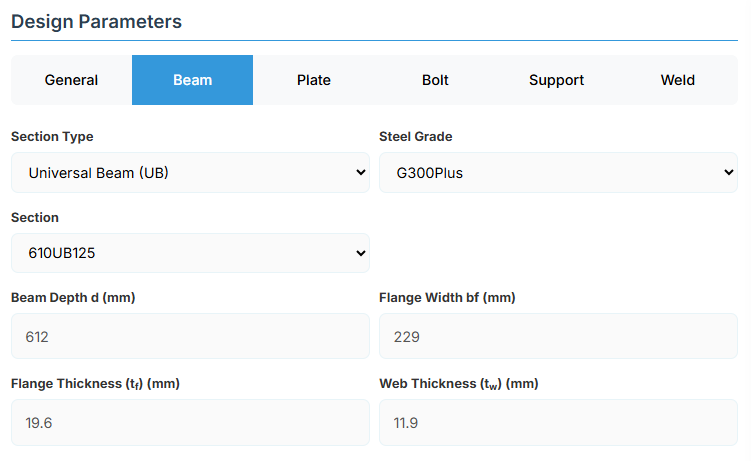
Section Type:
The application provides a comprehensive library of Australian and New Zealand standard sections. Per SCNZ 14.1, design strength limits vary based on section type (HR vs Welded). Section properties are automatically calculated from standard tables or user inputs. Sections must satisfy the material and section geometry requirements of NZS3404:1997 Sections 12.4 and 12.5, appropriate to the seismic ductility demand category of the frame.
- UB (Universal Beam) - Grades G350 and G300+
- UC (Universal Column) - Grades G350 and G300+
-
CWB (Custom Welded Beam) - Various grades.
- TFB (Tapered Flange Beam) - Grades G350 and G300+
- PB (Perimeter Welded Beams) - Grade G300M
- EB (Equivalent Welded Beams) - Grade G300M
- HB (Heavy Welded Beams) - Grade G300M
- HCB (High Capacity Beams) - Grade G300M
- HCBC (High Capacity Beam-Columns) - Grade G300M
- HCC (High Capacity Columns) - Grade G300M
- HP (Welded 'H' Piles) - Grade G300M
- NB (Narrow Welded Beams) - Grade G300M
- BP (Welded Bearing Piles) - Grade G300M
- SB (Standard Welded Beams) - Grade G300M
- SC (Standard Welded Columns) - Grade G300M
- LB (Light Welded Beams) - Grade G300M
- WS (Wide Sections) - Grade G300M
Section: Automatically populated based on the selected section type. The user can then select a specific section from the list.
When CWB is selected, manual inputs for depth (d), flange width (bf), flange thickness (tf), and web thickness (tw) become available.
↑ Back to Top
4. Plate Details

Plate Material
Select the steel grade for the end plate. Plate material properties (fyi and fui) are used in design calculations.
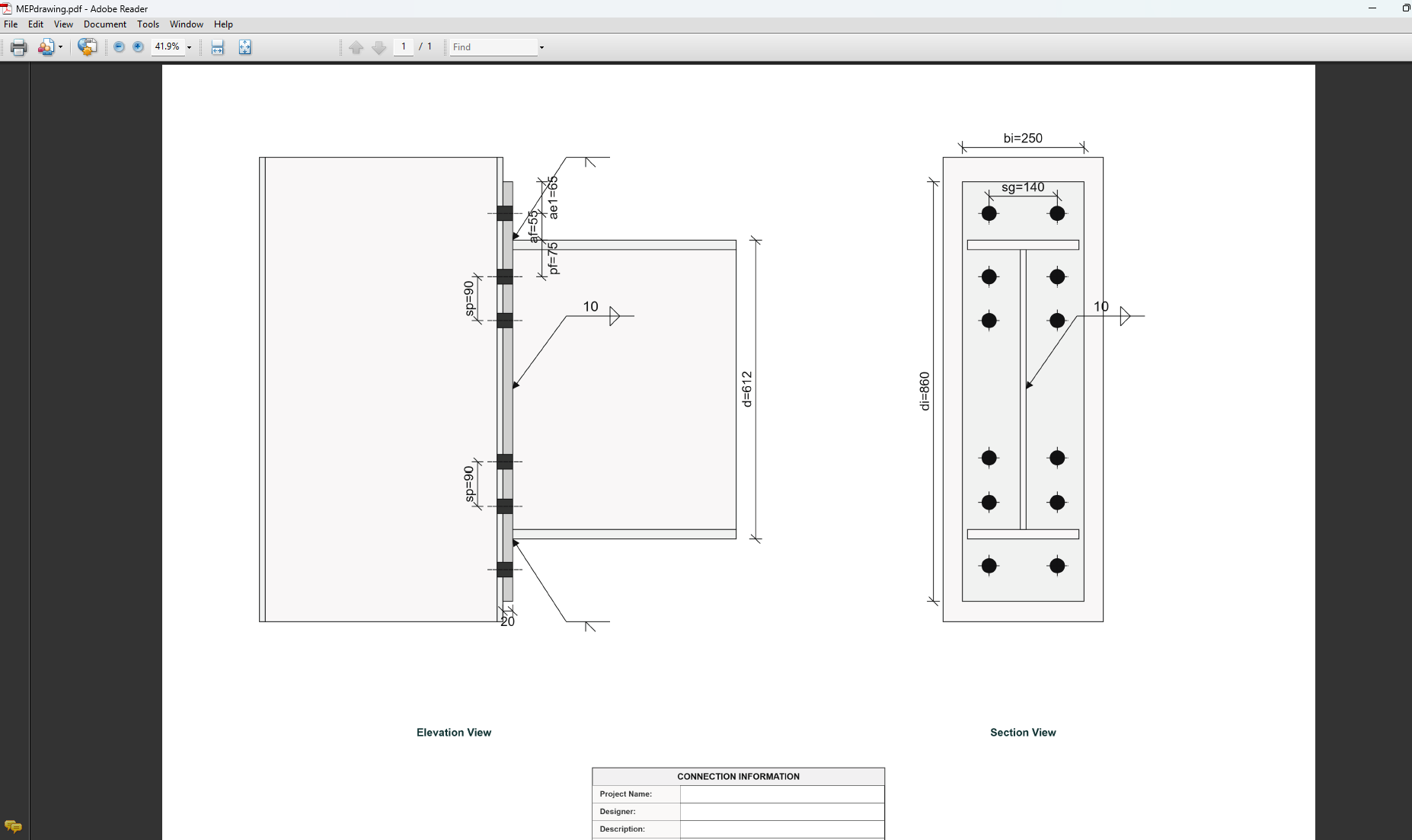
Plate Geometry
Define the dimensions of the end plate. These parameters directly affect the connection's load-carrying capacity and rigidity.
For primary members in limited ductile frames, end plates are sized for over-strength actions; for elastic frames, for design actions from analysis.
- Plate Depth (di): Height of the plate in mm (disabled, depends on af and ae1).
- Plate Width (bi): Width of the plate in mm.
- Plate Thickness (ti): Thickness of the plate in mm.
- Gusset Thickness (tgi): Thickness of the gusset plate in mm (for gusseted types).
↑ Back to Top
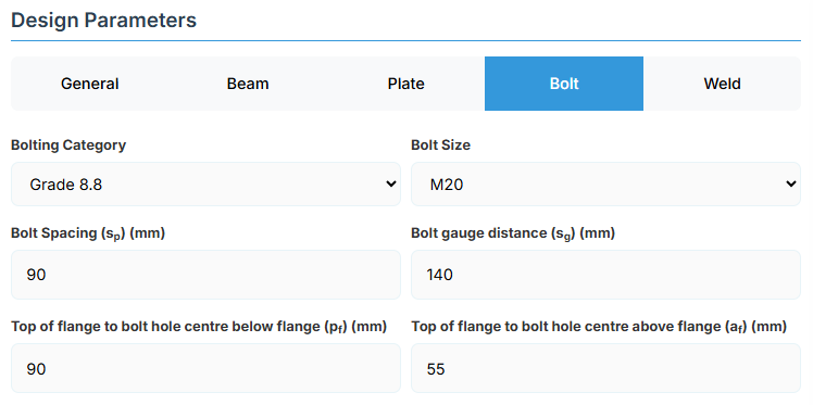
5. Bolt Configuration
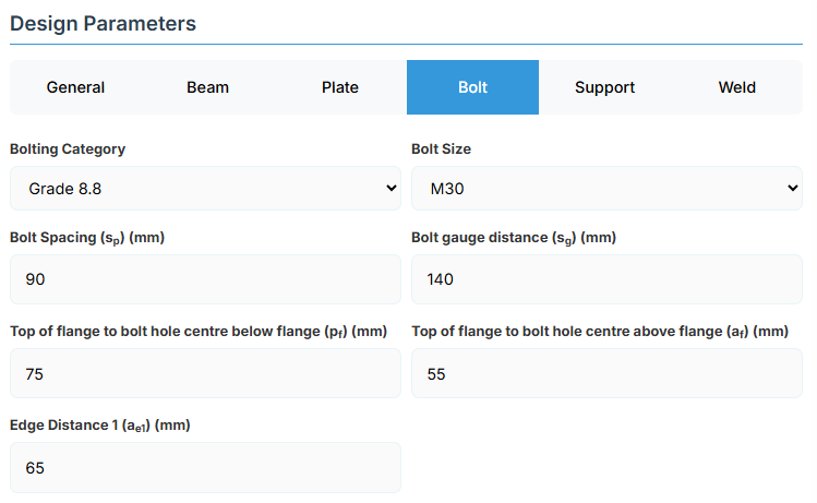
Bolt Category and Size
- Bolting Category: Class 8.8 - High-strength bolts with 830 MPa tensile strength.
-
Bolt Size:
Bolt Group Configuration
- Bolt Spacing (sp): Distance between bolt centerlines.
- Bolt Gauge Distance (sg): Lateral spacing between bolt columns.
- Top of Flange to Bolt Hole Centre Below Flange (pf): Distance in mm.
- Top of Flange to Bolt Hole Centre Above Flange (af): Distance in mm.
- Edge Distance 1 (ae1): Distance from bolt hole to the plate end.
↑ Back to Top
6. Support
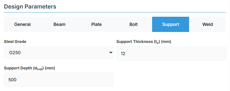
Support Member Details
- Steel Grade: G250, G300, G350, G400, or G450.
- Support Thickness (ts): Thickness of the supporting element (e.g., column flange).
- Support Depth (dsup): Depth of the supporting member.
The connection design assumes capacity not limited by column-side limit states. Load transfer stiffeners aligned with beam flanges are typically necessary. Where column flanges are thinner than beam end plates, flange doubler plates are usually required.
↑ Back to Top
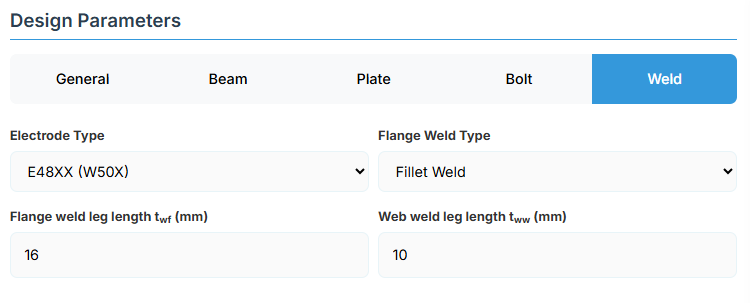
7. Weld Details
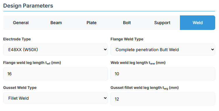
Weld Configuration
Define the weld parameters. Welds are sized to develop the design capacity of the web and flanges to enhance ductile behavior
-
Electrode Type:
- E41XX (W40X): 410 MPa yield strength.
- E48XX (W50X): 490 MPa yield strength (default).
-
Flange Weld Type:
- Fillet Weld: Symmetrical fillet welds either side of flanges (default). Designed for over-strength or design capacity based on frame ductility.
- Complete Penetration Butt Weld: Suitable without specific design.
- Flange Weld Leg Length (twf): Size in mm (if Fillet Weld).
- Web Weld Leg Length (tww): Size in mm.
-
Gusset Weld Type: For gusseted types.
- Fillet Weld: (default).
- Complete Penetration Butt Weld.
- Gusset Fillet Weld Leg Length (twg): Size in mm (if Fillet Weld).
↑ Back to Top
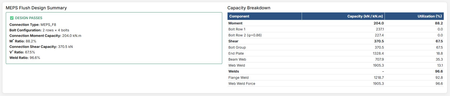
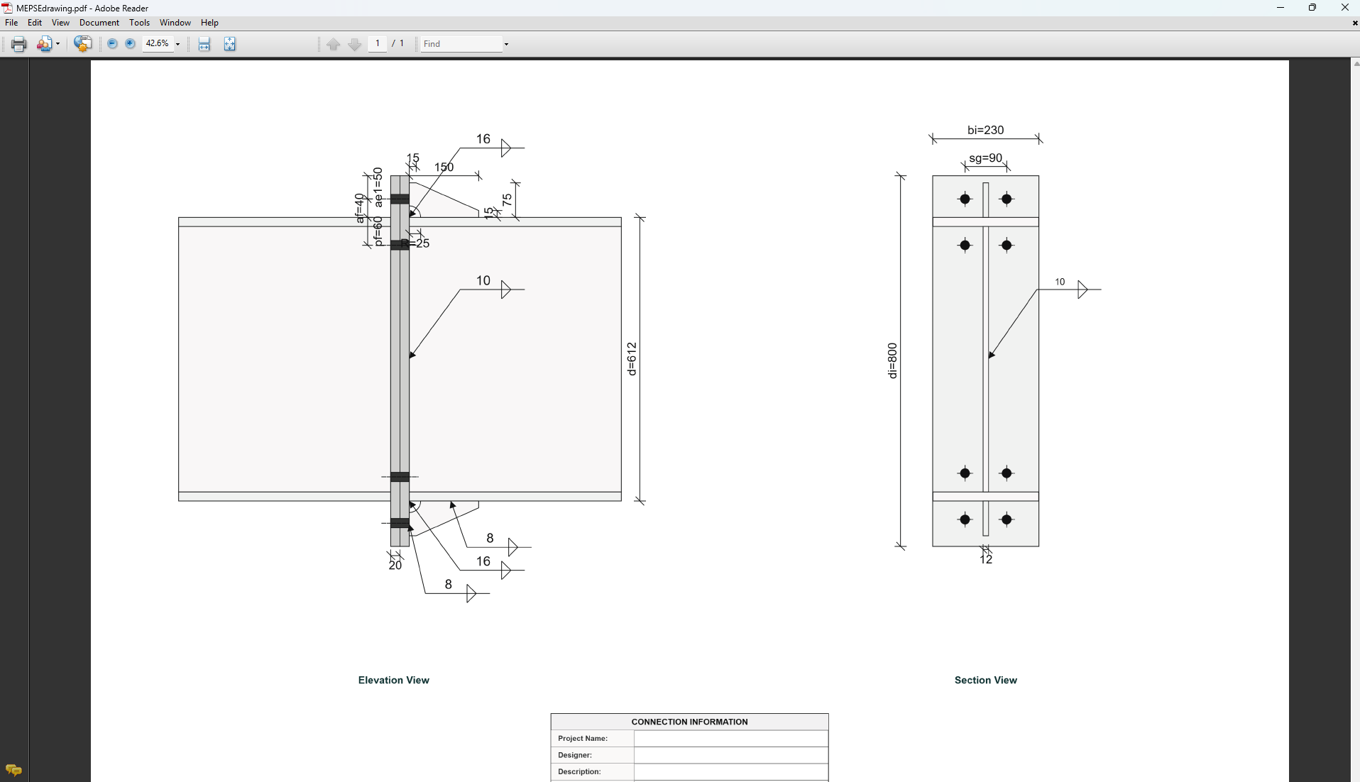
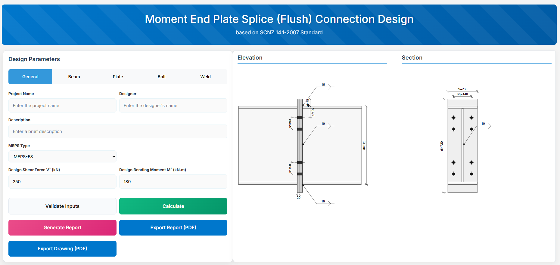
Moment End Plate Splice (Flush) Connection
1. Overview
The Moment End Plate Splice (Flush) Connection Design module provides a comprehensive approach for designing flush end-plate splices with a total of four, six, or eight bolts located on the inside face of the flanges in accordance with SCNZ 14.1-2007 Standard.
 ↑ Back to Top
2. General Setup
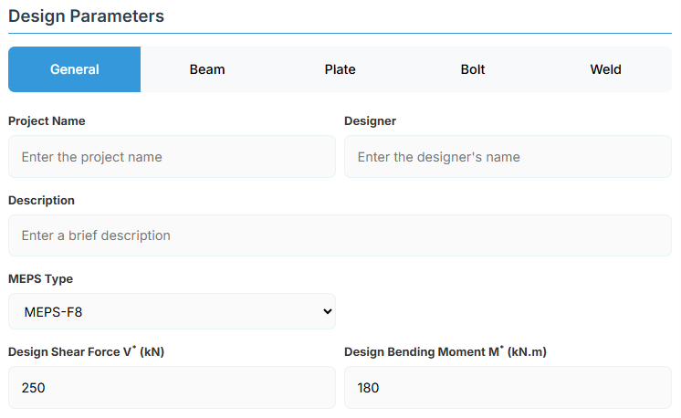
Project Information
This section captures essential metadata that will appear in your final design documentation.
- Project Name: Enter the name of the project. This helps identify the design file and appears in reports.
- Designer: The name of the person responsible for the connection design.
- Description: A brief overview of the connection design purpose or scope.
Connection Configuration
-
MEPS Type: Select the type of moment end plate splice connection:
- MEPS-F4: Flush 4-bolt configuration (default).
- MEPS-F6: Flush 6-bolt.
- MEPS-F8: Flush 8-bolt.
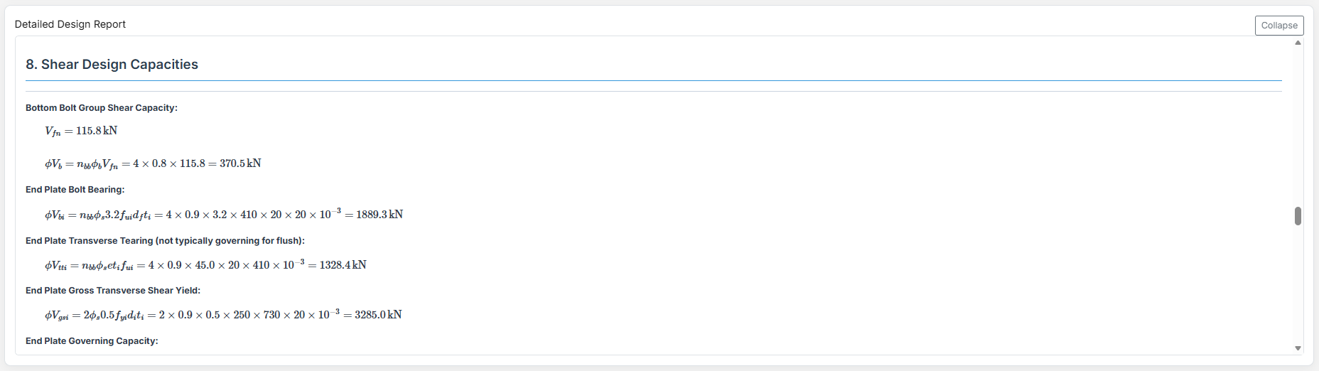
Loading Parameters
- Design Shear Force (V*): The primary design shear force in kN.
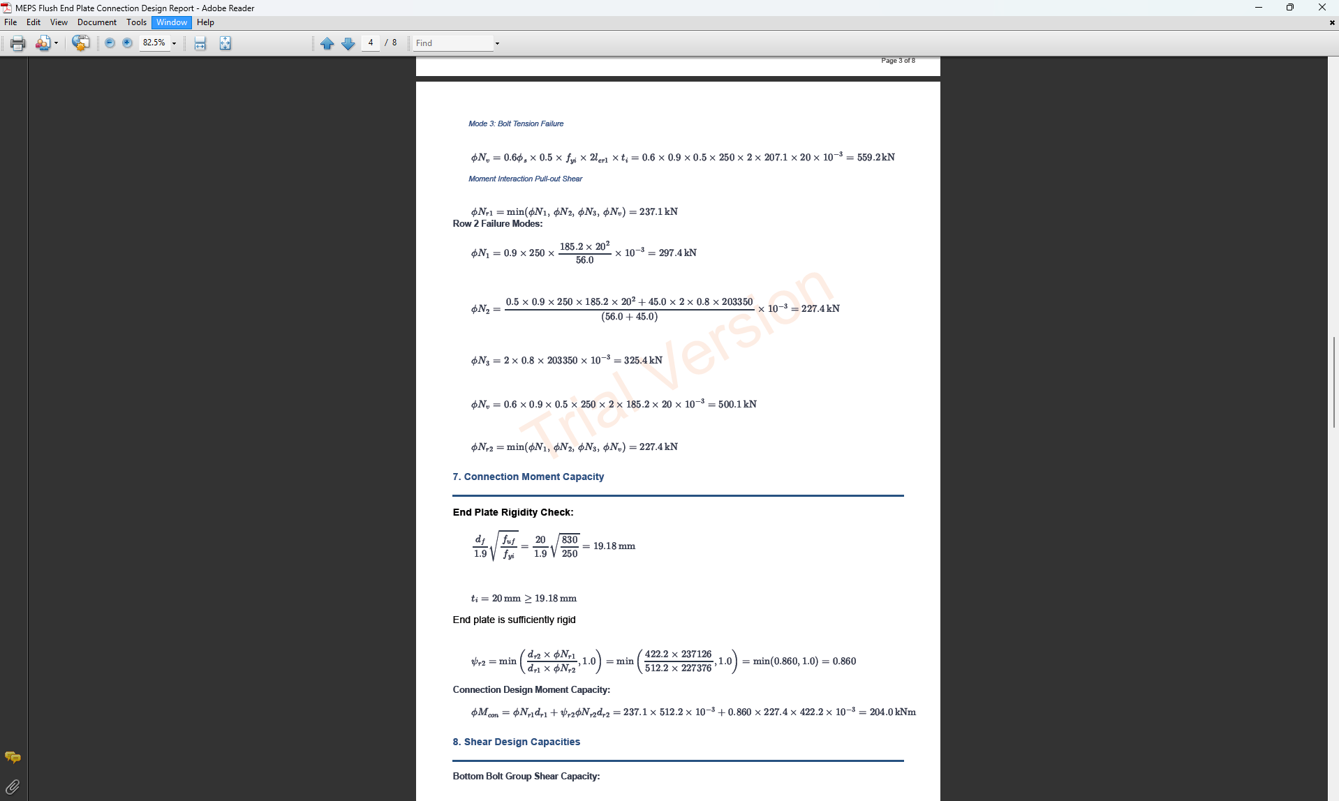
- Design Bending Moment (M*): The primary design bending moment in kN.m.
↑ Back to Top
3. Beam Properties
Section Type:
The application provides a comprehensive library of Australian and New Zealand standard sections. Per SCNZ 14.1, design strength limits vary based on section type (HR vs Welded). Section properties are automatically calculated from standard tables or user inputs. Sections must satisfy the section geometry requirements of NZS3404:1997 Section 12.5 for members of elastic frames.
- UB (Universal Beam) - Grades G350 and G300+
- UC (Universal Column) - Grades G350 and G300+
-
CWB (Custom Welded Beam) - Various grades.
- TFB (Tapered Flange Beam) - Grades G350 and G300+
- PB (Perimeter Welded Beams) - Grade G300M
- EB (Equivalent Welded Beams) - Grade G300M
- HB (Heavy Welded Beams) - Grade G300M
- HCB (High Capacity Beams) - Grade G300M
- HCBC (High Capacity Beam-Columns) - Grade G300M
- HCC (High Capacity Columns) - Grade G300M
- HP (Welded 'H' Piles) - Grade G300M
- NB (Narrow Welded Beams) - Grade G300M
- BP (Welded Bearing Piles) - Grade G300M
- SB (Standard Welded Beams) - Grade G300M
- SC (Standard Welded Columns) - Grade G300M
- LB (Light Welded Beams) - Grade G300M
- WS (Wide Sections) - Grade G300M
Section: Automatically populated based on the selected section type. The user can then select a specific section from the list.
When CWB is selected, manual inputs for depth (d), flange width (bf), flange thickness (tf), and web thickness (tw) become available.
↑ Back to Top
4. Plate Details
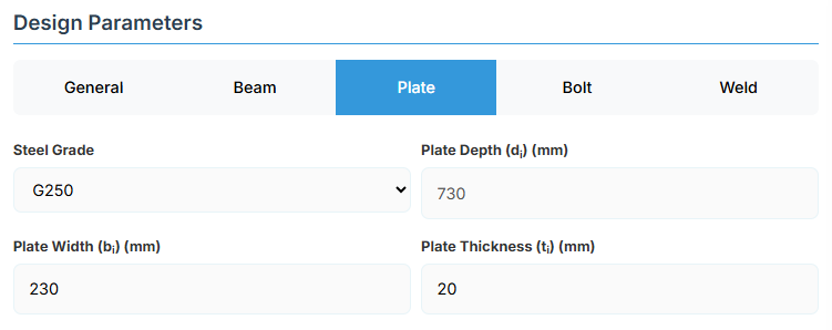
Plate Material
Select the steel grade for the end plate. Plate material properties (fyi and fui) are used in design calculations.
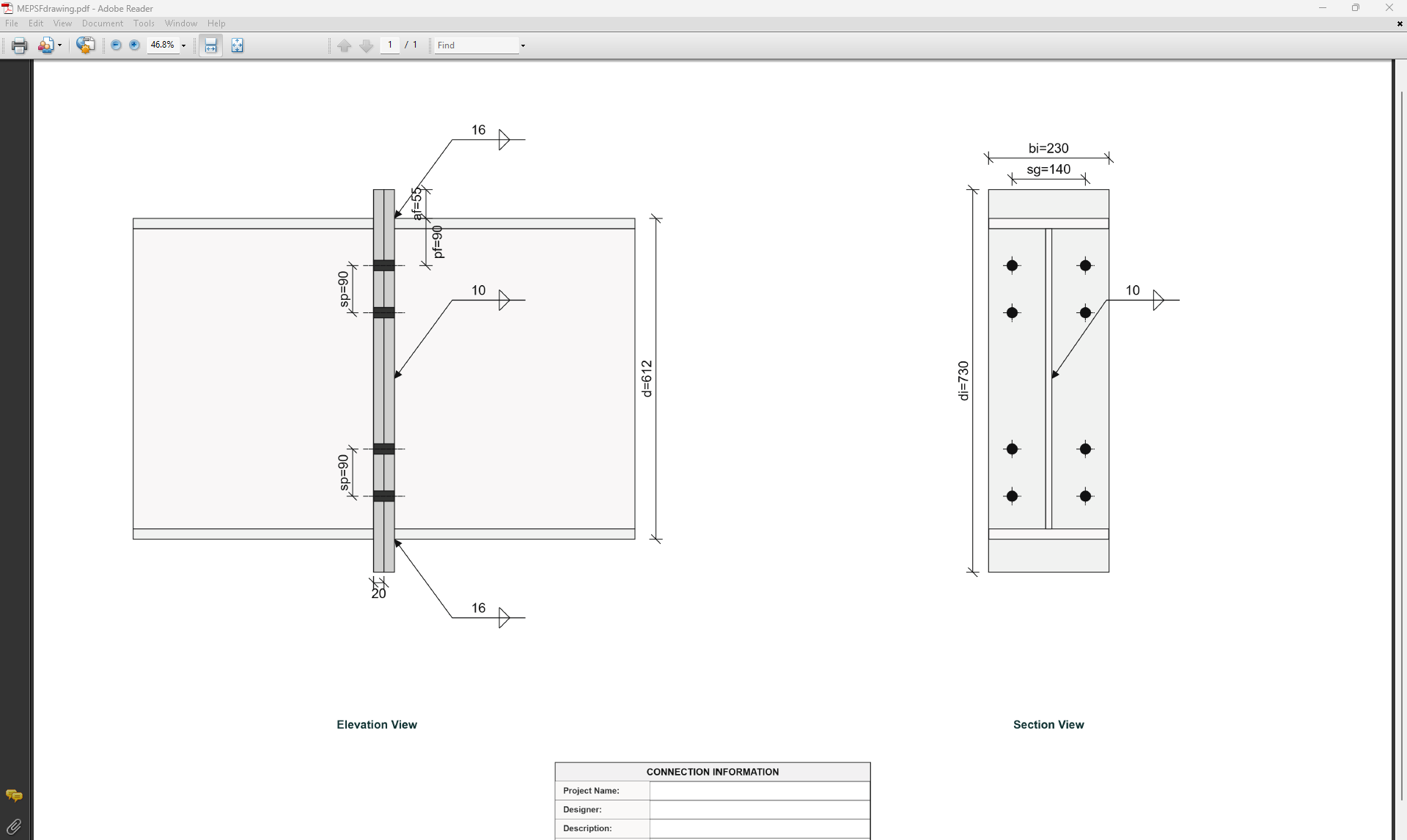
Plate Geometry
Define the dimensions of the end plate. These parameters directly affect the connection's load-carrying capacity. End plates for MEPS-F connections are sized assuming equal thickness end plates.
- Plate Depth (di): Height of the plate in mm (disabled, depends on af).
- Plate Width (bi): Width of the plate in mm.
- Plate Thickness (ti): Thickness of the plate in mm.
↑ Back to Top
5. Bolt Configuration
Bolt Category and Size
- Bolting Category: Class 8.8 - High-strength bolts with 830 MPa tensile strength.
-
Bolt Size:
Bolt Group Configuration
- Bolt Spacing (sp): Distance between bolt centerlines.
- Bolt Gauge Distance (sg): Lateral spacing between bolt columns.
- Top of Flange to Bolt Hole Centre Below Flange (pf): Distance in mm.
- Top of Flange to Bolt Hole Centre Above Flange (af): Distance in mm.
↑ Back to Top
6. Weld Details
Weld Configuration
Define the weld parameters. The welds are sized to develop the design capacity of the web and flanges to enhance ductile behaviour.
-
Electrode Type:
- E41XX (W40X): 410 MPa yield strength.
- E48XX (W50X): 490 MPa yield strength (default).
-
Flange Weld Type:
- Fillet Weld: Symmetrical fillet welds placed either side of the flanges (default).
- Complete Penetration Butt Weld: Suitable for all members without specific design.
- Flange Weld Leg Length (twf): Size of the fillet weld on the flanges in mm (if Fillet Weld selected).
- Web Weld Leg Length (tww): Size of the fillet weld on the web in mm.
↑ Back to Top
Moment End Plate Splice (Extended) Connection
1. Overview
The Moment End Plate Splice (Extended) Connection Design module provides a comprehensive approach for designing extended end-plate splices with a total of eight, ten, or twelve bolts in accordance with SCNZ 14.1-2007 Standard.
 ↑ Back to Top
2. General Setup
Project Information
This section captures essential metadata that will appear in your final design documentation.
- Project Name: Enter the name of the project. This helps identify the design file and appears in reports.
- Designer: The name of the person responsible for the connection design.
- Description: A brief overview of the connection design purpose or scope.
Connection Configuration
-
MEP Type: Select the type of moment end plate splice connection:
- MEPS-E8: Extended 8-bolt configuration (default).
- MEPS-G8: Gusseted 8-bolt.
- MEPS-E10: Extended 10-bolt.
- MEPS-G10: Gusseted 10-bolt.
- MEPS-E12: Extended 12-bolt.
- MEPS-G12: Gusseted 12-bolt.
Loading Parameters
- Design Shear Force (V*): The primary design shear force in kN.
- Design Bending Moment (M*): The primary design bending moment in kN.m.
↑ Back to Top
3. Beam Properties
Section Type:
The application provides a comprehensive library of Australian and New Zealand standard sections. Per SCNZ 14.1, design strength limits vary based on section type (HR vs Welded). Section properties are automatically calculated from standard tables or user inputs. Sections must satisfy the section geometry requirements of NZS3404:1997 Section 12.5 for members of elastic frames.
- UB (Universal Beam) - Grades G350 and G300+
- UC (Universal Column) - Grades G350 and G300+
-
CWB (Custom Welded Beam) - Various grades.
- TFB (Tapered Flange Beam) - Grades G350 and G300+
- PB (Perimeter Welded Beams) - Grade G300M
- EB (Equivalent Welded Beams) - Grade G300M
- HB (Heavy Welded Beams) - Grade G300M
- HCB (High Capacity Beams) - Grade G300M
- HCBC (High Capacity Beam-Columns) - Grade G300M
- HCC (High Capacity Columns) - Grade G300M
- HP (Welded 'H' Piles) - Grade G300M
- NB (Narrow Welded Beams) - Grade G300M
- BP (Welded Bearing Piles) - Grade G300M
- SB (Standard Welded Beams) - Grade G300M
- SC (Standard Welded Columns) - Grade G300M
- LB (Light Welded Beams) - Grade G300M
- WS (Wide Sections) - Grade G300M
Section: Automatically populated based on the selected section type. The user can then select a specific section from the list.
When CWB is selected, manual inputs for depth (d), flange width (bf), flange thickness (tf), and web thickness (tw) become available.
↑ Back to Top
4. Plate Details
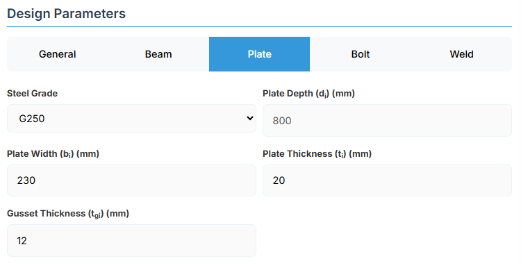
Plate Material
Select the steel grade for the end plate. Plate material properties (fyi and fui) are used in design calculations.
Plate Geometry
Define the dimensions of the end plate. These parameters directly affect the connection's load-carrying capacity. End plates for MEPS-E connections are sized assuming equal thickness end plates.
- Plate Depth (di): Height of the plate in mm (disabled, depends on af and ae1).
- Plate Width (bi): Width of the plate in mm.
- Plate Thickness (ti): Thickness of the plate in mm.
- Gusset Thickness (tgi): Thickness of the gusset plate in mm (for gusseted types).
↑ Back to Top
5. Bolt Configuration
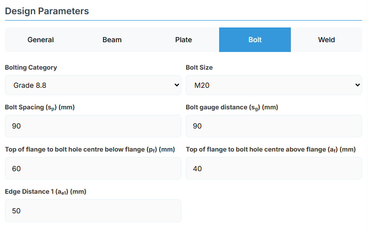
Bolt Category and Size
- Bolting Category: Class 8.8 - High-strength bolts with 830 MPa tensile strength.
-
Bolt Size:
Bolt Group Configuration
- Bolt Spacing (sp): Distance between bolt centerlines.
- Bolt Gauge Distance (sg): Lateral spacing between bolt columns.
- Top of Flange to Bolt Hole Centre Below Flange (pf): Distance in mm.
- Top of Flange to Bolt Hole Centre Above Flange (af): Distance in mm.
- Edge Distance 1 (ae1): Distance from bolt hole to the plate end.
↑ Back to Top
6. Weld Details
Weld Configuration
Define the weld parameters. The welds are sized to develop the design capacity of the web and flanges to enhance ductile behaviour.
-
Electrode Type:
- E41XX (W40X): 410 MPa yield strength.
- E48XX (W50X): 490 MPa yield strength (default).
-
Flange Weld Type:
- Fillet Weld: Symmetrical fillet welds placed either side of the flanges (default).
- Complete Penetration Butt Weld: Suitable for all members without specific design.
- Flange Weld Leg Length (twf): Size of the fillet weld on the flanges in mm (if Fillet Weld selected).
- Web Weld Leg Length (tww): Size of the fillet weld on the web in mm.
-
Gusset Weld Type:
- Fillet Weld: (default).
- Complete Penetration Butt Weld.
- Gusset Fillet Weld Leg Length (twg): Size in mm (if Fillet Weld).
↑ Back to Top
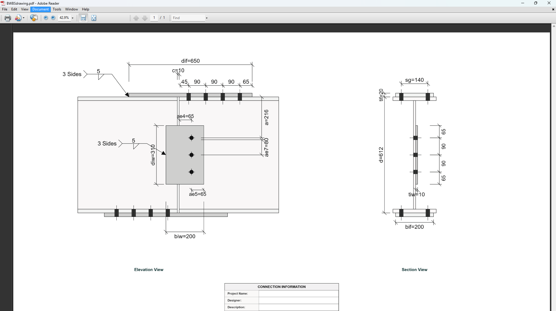
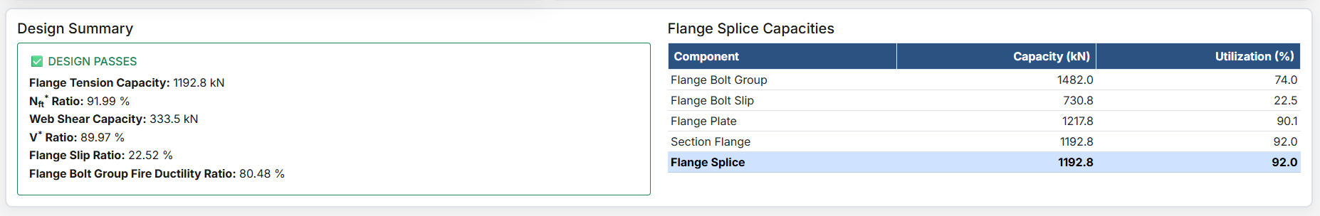
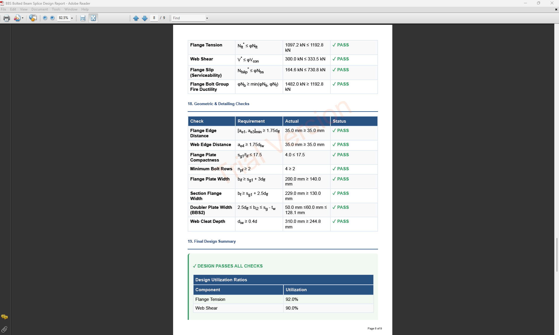
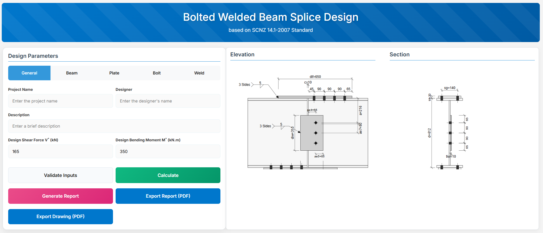
Bolted Welded Beam Splice Design
1. Overview
The Bolted Welded Beam Splice Design module provides a comprehensive approach for designing bolted welded beam splices in accordance with SCNZ 14.1-2007 Standard.
The design possesses capacity to satisfy gravity and seismic design actions derived from relevant design or over-strength actions of primary members of seismic resisting frames.
 ↑ Back to Top
2. General Setup
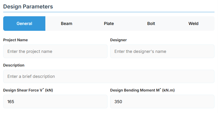
Project Information
This section captures essential metadata that will appear in your final design documentation.
- Project Name: Enter the name of the project. This helps identify the design file and appears in reports.
- Designer: The name of the person responsible for the connection design.
- Description: A brief overview of the connection design purpose or scope.
Loading Parameters
- Design Shear Force (V*): The primary design shear force in kN.
- Design Bending Moment (M*): The primary design bending moment in kN.m.
↑ Back to Top
3. Beam Properties
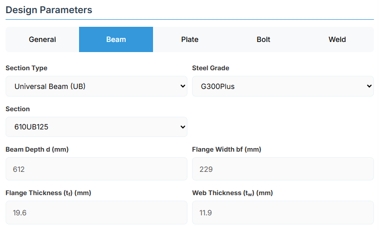
Section Type:
The application provides a comprehensive library of Australian and New Zealand standard sections. Per SCNZ 14.1, design strength limits vary based on section type (HR vs Welded). Section properties are automatically calculated from standard tables or user inputs. Doubly symmetrical I sections only.
- UB (Universal Beam) - Grades G350 and G300+
- UC (Universal Column) - Grades G350 and G300+
-
CWB (Custom Welded Beam) - Various grades.
- TFB (Tapered Flange Beam) - Grades G350 and G300+
- PB (Perimeter Welded Beams) - Grade G300M
- EB (Equivalent Welded Beams) - Grade G300M
- HB (Heavy Welded Beams) - Grade G300M
- HCB (High Capacity Beams) - Grade G300M
- HCBC (High Capacity Beam-Columns) - Grade G300M
- HCC (High Capacity Columns) - Grade G300M
- HP (Welded 'H' Piles) - Grade G300M
- NB (Narrow Welded Beams) - Grade G300M
- BP (Welded Bearing Piles) - Grade G300M
- SB (Standard Welded Beams) - Grade G300M
- SC (Standard Welded Columns) - Grade G300M
- LB (Light Welded Beams) - Grade G300M
- WS (Wide Sections) - Grade G300M
Section: Automatically populated based on the selected section type. The user can then select a specific section from the list.
When CWB is selected, manual inputs for depth (d), flange width (bf), flange thickness (tf), and web thickness (tw) become available.
↑ Back to Top
4. Plate Details
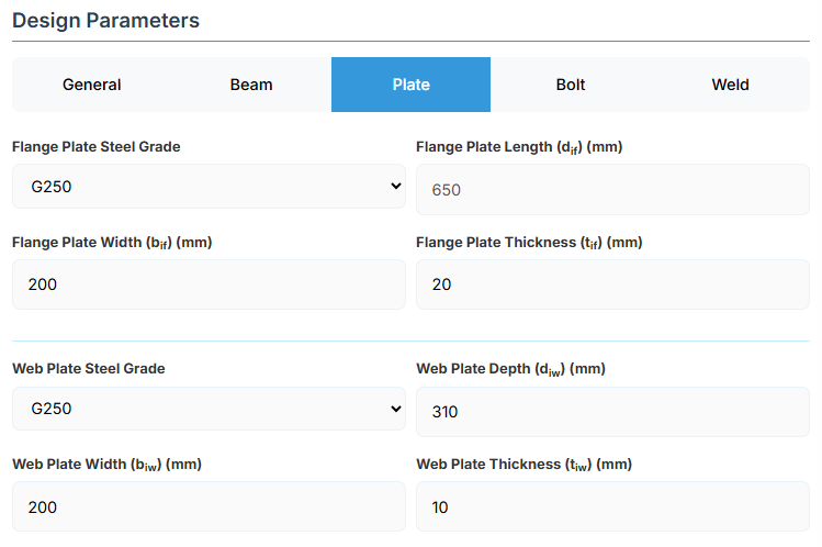
Flange Plate
- Flange Plate Steel Grade: G250, G300, G400, G350, or G450.
- Flange Plate Length (dif): Length of the flange plate in mm (disabled, depends on npf, spf, c and ae1).
- Flange Plate Width (bif): Width of the flange plate in mm.
- Flange Plate Thickness (tif): Thickness of the flange plate in mm.
Web Plate
- Web Plate Steel Grade: G250, G300, G400, G350, or G450.
- Web Plate Depth (diw): Depth of the web plate in mm.
- Web Plate Width (biw): Width of the web plate in mm.
- Web Plate Thickness (tiw): Thickness of the web plate in mm.
↑ Back to Top
5. Bolt Configuration
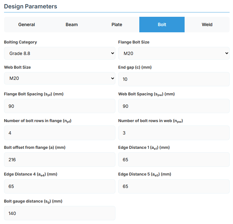
Bolt Properties
- Bolting Category: Class 8.8 - High-strength bolts with 830 MPa tensile strength.
-
Flange Bolt Size:
-
Web Bolt Size:
Bolt Layout
- End Gap (c): Gap between beam ends in mm.
- Flange Bolt Spacing (spf): Spacing between flange bolts in mm.
- Web Bolt Spacing (spw): Spacing between web bolts in mm.
- Number of Bolt Rows in Flange (npf): Number of rows.
- Number of Bolt Rows in Web (npw): Number of rows.
- Bolt Offset from Flange (a): Offset in mm.
- Edge Distance 1 (ae1): Edge distance in mm.
- Edge Distance 4 (ae4): Edge distance in mm.
- Edge Distance 5 (ae5): Edge distance in mm.
- Bolt Gauge Distance (sg): Gauge in mm.
↑ Back to Top
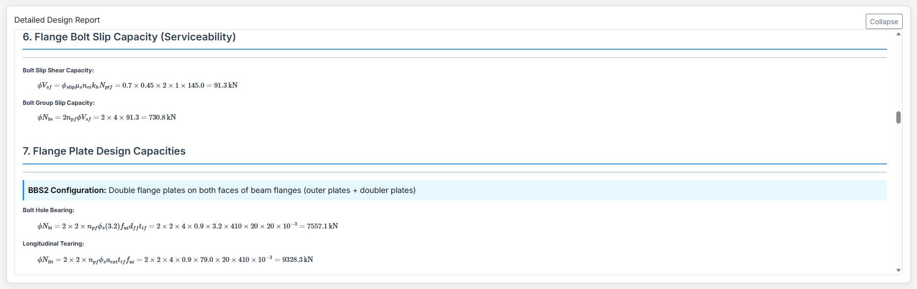
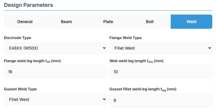
6. Weld Details
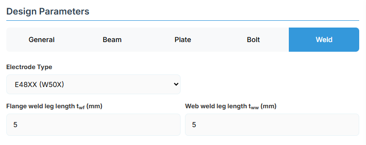
Weld Configuration
Define the weld parameters. The welds are sized to develop the design capacity of the web and flanges to enhance ductile behaviour under fire conditions.
-
Electrode Type:
- E41XX (W40X): 410 MPa yield strength.
- E48XX (W50X): 490 MPa yield strength (default).
- Flange Weld Leg Length (twf): Size of the fillet weld on the flanges in mm.
- Web Weld Leg Length (tww): Size of the fillet weld on the web in mm.
↑ Back to Top
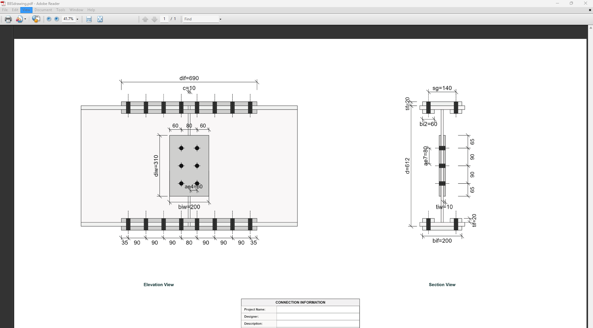
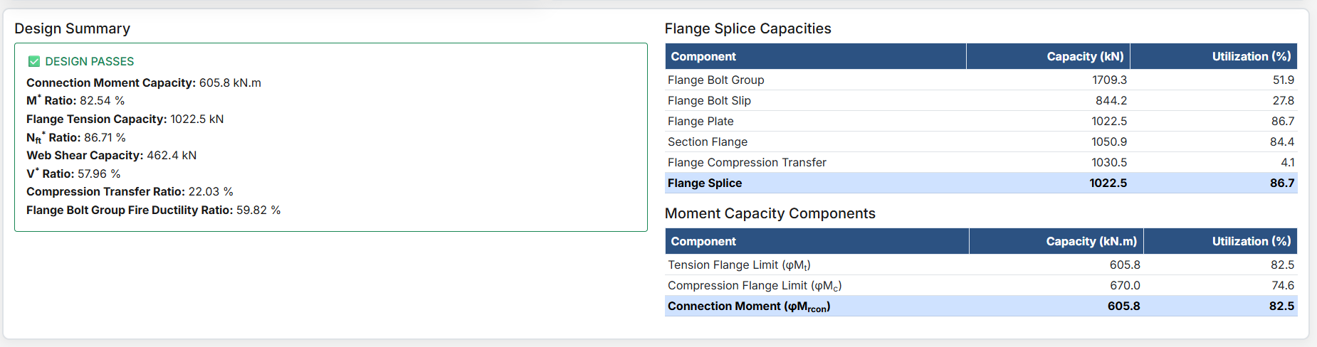
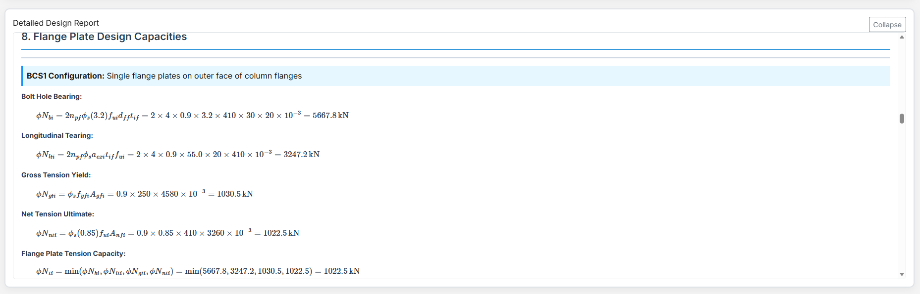
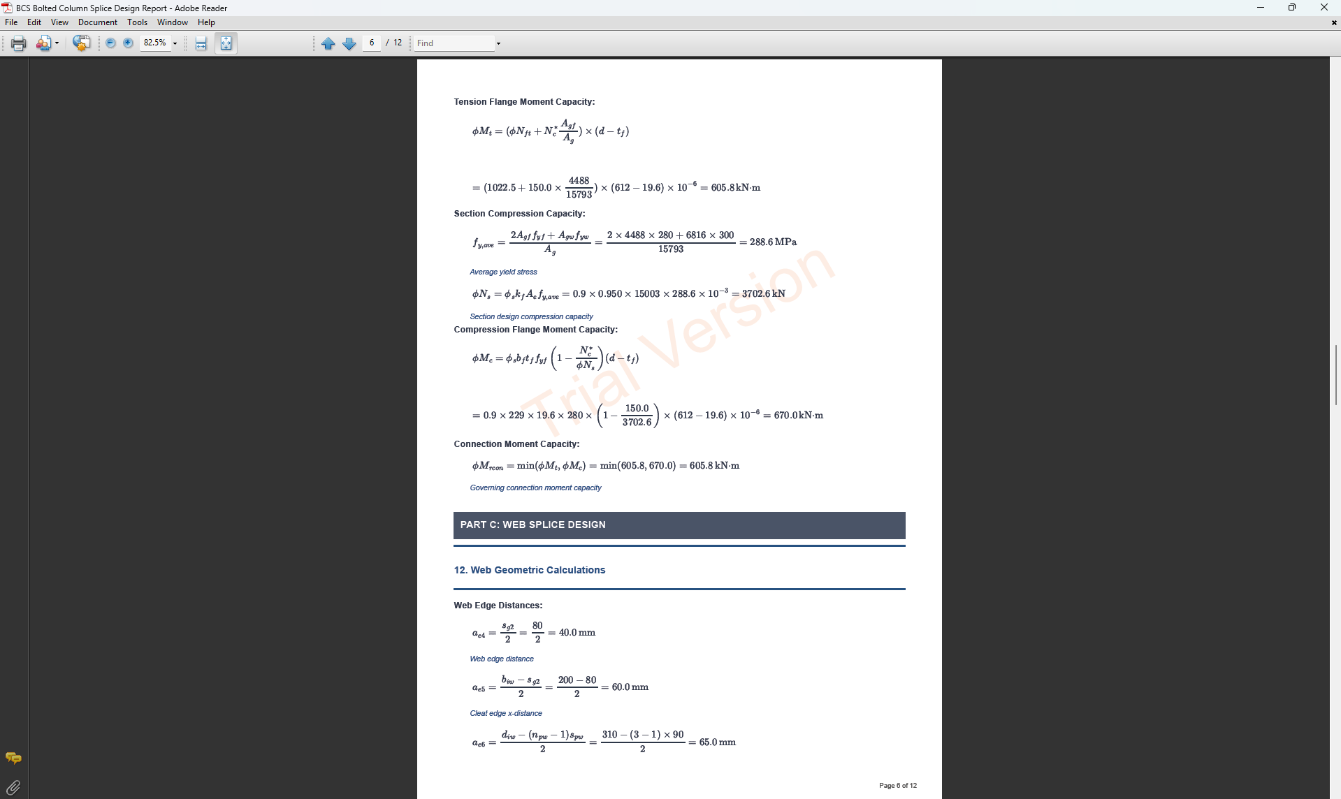
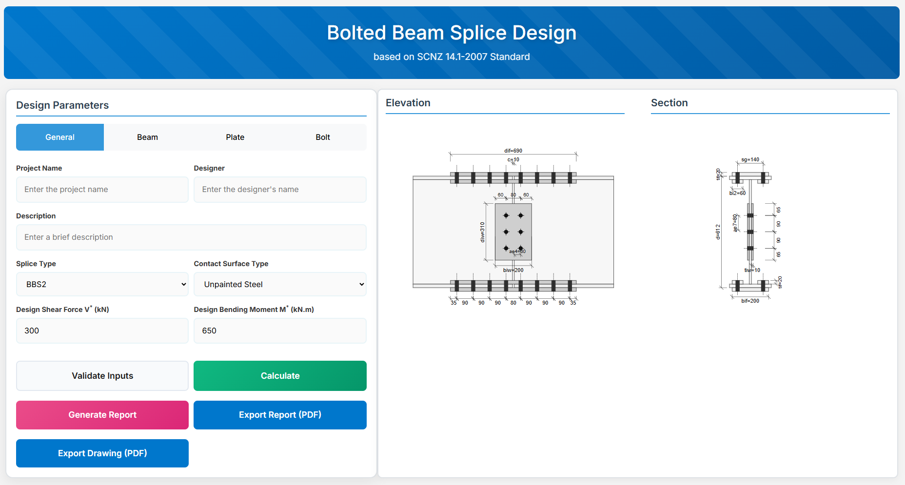
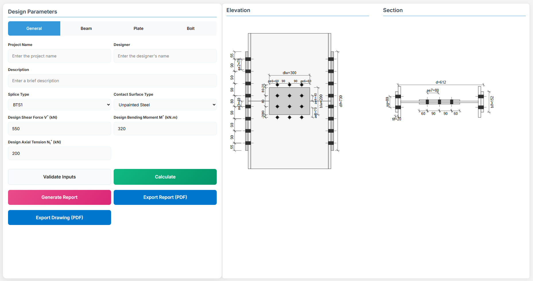
Bolted Beam Splice Design
1. Overview
The Bolted Beam Splice Design module provides a comprehensive approach for designing bolted beam splices in accordance with SCNZ 14.1-2007 Standard. The design possesses capacity to satisfy gravity and seismic design actions derived from relevant design or over-strength actions of primary members of seismic resisting frames. The splices are located away from potential seismic yielding regions of the member and maintain ductile performance under fire restraint conditions.
 ↑ Back to Top
2. General Setup
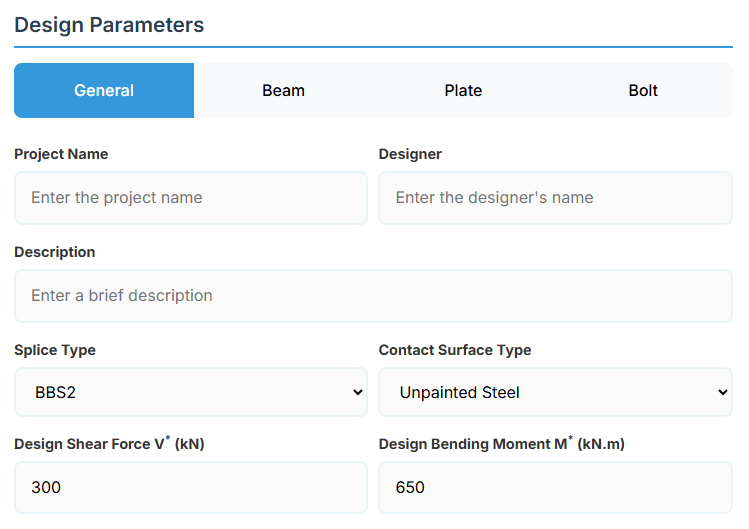
Project Information
This section captures essential metadata that will appear in your final design documentation.
- Project Name: Enter the name of the project. This helps identify the design file and appears in reports.
- Designer: The name of the person responsible for the connection design.
- Description: A brief overview of the connection design purpose or scope.
Connection Configuration
-
Splice Type: Select the type of bolted beam splice:
- BBS1: Single flange plates located on the outer face of the beam flanges (default).
- BBS2: Flange plates of equal thickness located on both faces of the beam flanges.
-
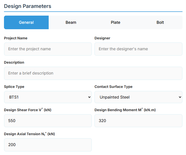
Contact Surface Type: Select the surface type for slip factor calculation:
- Unpainted Steel: Slip factor μs = 0.45 (default).
- Inorganic Zinc Silicate: Slip factor μs = 0.5.
- Alkyd Primer: Slip factor μs = 0.11.
Loading Parameters
- Design Shear Force (V*): The primary design shear force in kN.
- Design Bending Moment (M*): The primary design bending moment in kN.m.
↑ Back to Top
3. Beam Properties

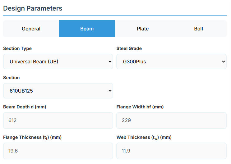
Section Type:
The application provides a comprehensive library of Australian and New Zealand standard sections. Per SCNZ 14.1, design strength limits vary based on section type (HR vs Welded). Section properties are automatically calculated from standard tables or user inputs. Doubly symmetrical I sections only.
- UB (Universal Beam) - Grades G350 and G300+
- UC (Universal Column) - Grades G350 and G300+
-
CWB (Custom Welded Beam) - Various grades.
- TFB (Tapered Flange Beam) - Grades G350 and G300+
- PB (Perimeter Welded Beams) - Grade G300M
- EB (Equivalent Welded Beams) - Grade G300M
- HB (Heavy Welded Beams) - Grade G300M
- HCB (High Capacity Beams) - Grade G300M
- HCBC (High Capacity Beam-Columns) - Grade G300M
- HCC (High Capacity Columns) - Grade G300M
- HP (Welded 'H' Piles) - Grade G300M
- NB (Narrow Welded Beams) - Grade G300M
- BP (Welded Bearing Piles) - Grade G300M
- SB (Standard Welded Beams) - Grade G300M
- SC (Standard Welded Columns) - Grade G300M
- LB (Light Welded Beams) - Grade G300M
- WS (Wide Sections) - Grade G300M
Section: Automatically populated based on the selected section type. The user can then select a specific section from the list.
When CWB is selected, manual inputs for depth (d), flange width (bf), flange thickness (tf), and web thickness (tw) become available.
↑ Back to Top
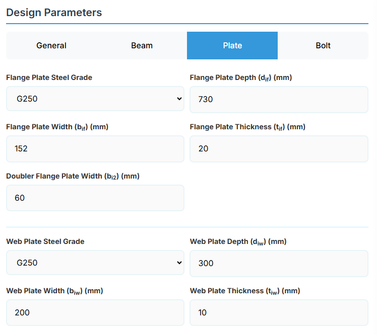
4. Plate Details

Flange Plate
- Flange Plate Steel Grade: G250, G300, G400, G350, or G450.
- Flange Plate Depth (dif): Depth of the flange plate in mm.
- Flange Plate Width (bif): Width of the flange plate in mm.
- Flange Plate Thickness (tif): Thickness of the flange plate in mm.
- Doubler Flange Plate Width (bi2): Width of the doubler flange plate in mm (for BBS2).
Web Plate
- Web Plate Steel Grade: G250, G300, G400, G350, or G450.
- Web Plate Depth (diw): Depth of the web plate in mm.
- Web Plate Width (biw): Width of the web plate in mm.
- Web Plate Thickness (tiw): Thickness of the web plate in mm.
↑ Back to Top
5. Bolt Configuration
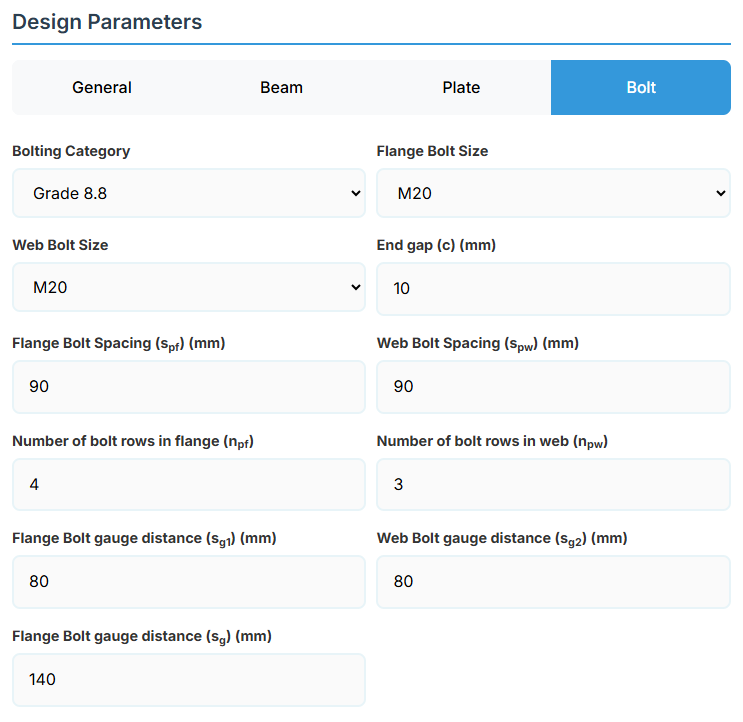
Bolt Properties
- Bolting Category: Class 8.8 - High-strength bolts with 830 MPa tensile strength.
-
Flange Bolt Size:
-
Web Bolt Size:
Bolt Layout
- End Gap (c): Gap between beam ends in mm.
- Flange Bolt Spacing (spf): Spacing between flange bolts in mm.
- Web Bolt Spacing (spw): Spacing between web bolts in mm.
- Number of Bolt Rows in Flange (npf): Number of rows.
- Number of Bolt Rows in Web (npw): Number of rows.
- Flange Bolt Gauge Distance (sg1): Gauge in mm.
- Web Bolt Gauge Distance (sg2): Gauge in mm.
- Flange Bolt Gauge Distance (sg): Gauge in mm.
↑ Back to Top
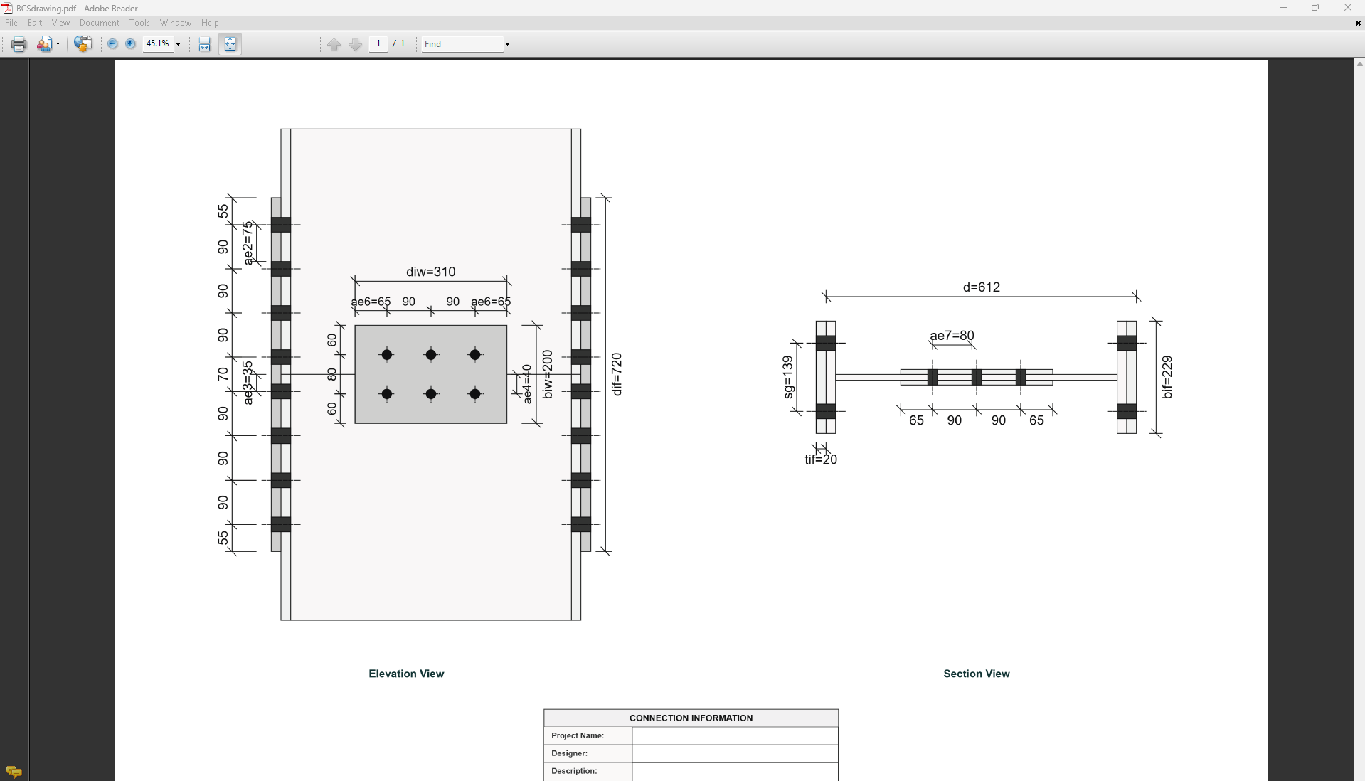
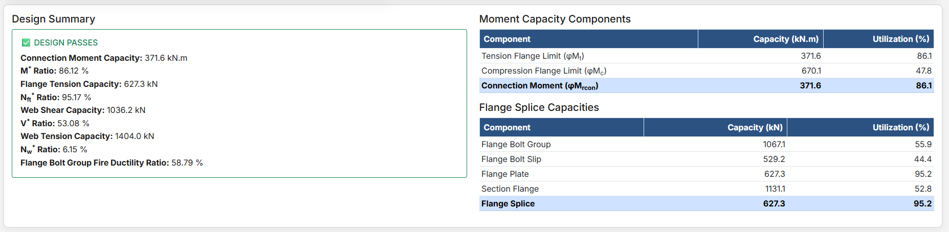
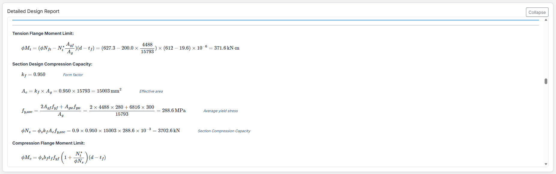
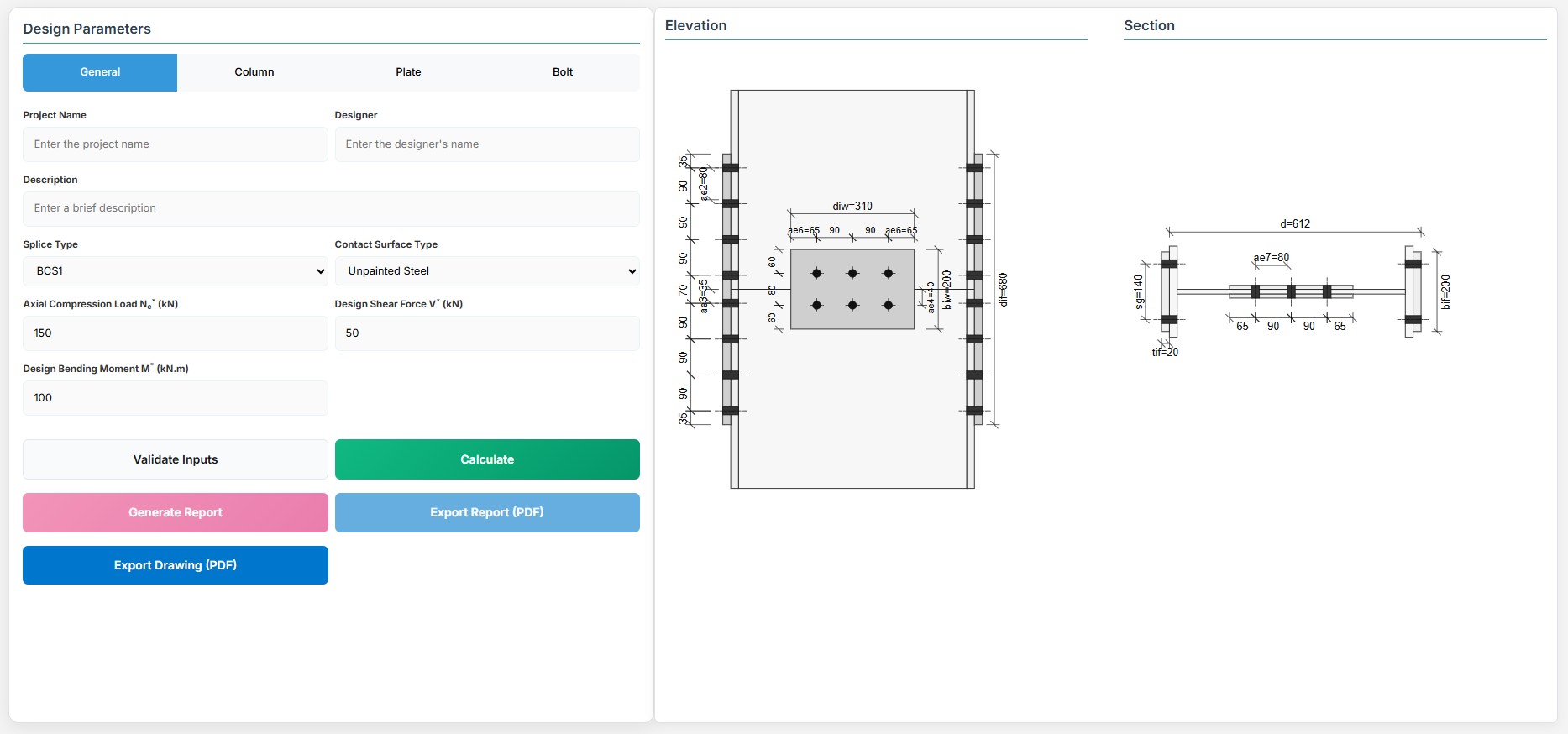
Bolted Compression Splice Design
1. Overview
The Bolted Compression Splice Design module provides a comprehensive approach for designing bolted compression splices for columns in accordance with SCNZ 14.1-2007 Standard.
 ↑ Back to Top
2. General Setup
Project Information
This section captures essential metadata that will appear in your final design documentation.
- Project Name: Enter the name of the project. This helps identify the design file and appears in reports.
- Designer: The name of the person responsible for the connection design.
- Description: A brief overview of the connection design purpose or scope.
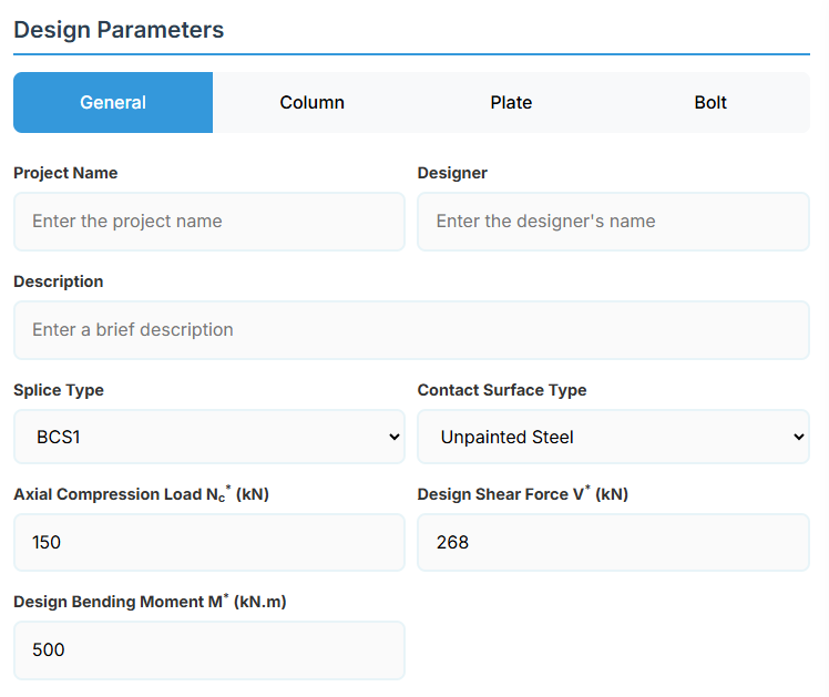
Connection Configuration
-
Splice Type: Select the type of bolted compression splice:
-
Contact Surface Type: Select the surface type for slip factor calculation:
- Unpainted Steel: Slip factor μs = 0.45 (default).
- Inorganic Zinc Silicate: Slip factor μs = 0.5.
- Alkyd Primer: Slip factor μs = 0.11.
Loading Parameters
- Axial Compression Load Nc* (kN): The design axial compression load.
- Design Shear Force (V*): The primary design shear force in kN.
- Design Bending Moment (M*): The primary design bending moment in kN.m.
↑ Back to Top
3. Column Properties
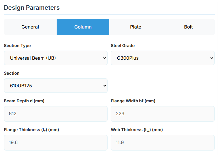
Section Type:
The application provides a comprehensive library of Australian and New Zealand standard sections. Per SCNZ 14.1, design strength limits vary based on section type (HR vs Welded). Section properties are automatically calculated from standard tables or user inputs.
- UB (Universal Beam) - Grades G350 and G300+
- UC (Universal Column) - Grades G350 and G300+
-
CWB (Custom Welded Beam) - Various grades.
- TFB (Tapered Flange Beam) - Grades G350 and G300+
- PB (Perimeter Welded Beams) - Grade G300M
- EB (Equivalent Welded Beams) - Grade G300M
- HB (Heavy Welded Beams) - Grade G300M
- HCB (High Capacity Beams) - Grade G300M
- HCBC (High Capacity Beam-Columns) - Grade G300M
- HCC (High Capacity Columns) - Grade G300M
- HP (Welded 'H' Piles) - Grade G300M
- NB (Narrow Welded Beams) - Grade G300M
- BP (Welded Bearing Piles) - Grade G300M
- SB (Standard Welded Beams) - Grade G300M
- SC (Standard Welded Columns) - Grade G300M
- LB (Light Welded Beams) - Grade G300M
- WS (Wide Sections) - Grade G300M
Section: Automatically populated based on the selected section type. The user can then select a specific section from the list.
When CWB is selected, manual inputs for depth (d), flange width (bf), flange thickness (tf), and web thickness (tw) become available.
↑ Back to Top
4. Plate Details
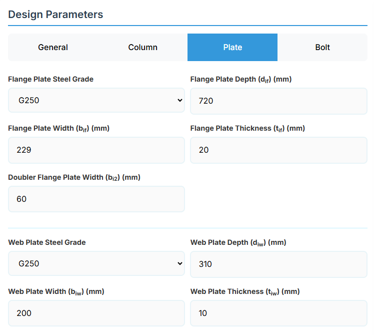
Flange Plate
- Flange Plate Steel Grade: G250, G300, G400, G350, or G450.
- Flange Plate Depth (dif): Depth of the flange plate in mm.
- Flange Plate Width (bif): Width of the flange plate in mm.
- Flange Plate Thickness (tif): Thickness of the flange plate in mm.
- Doubler Flange Plate Width (bi2): Width of the doubler flange plate in mm (for BCS2).
Web Plate
- Web Plate Steel Grade: G250, G300, G400, G350, or G450.
- Web Plate Depth (diw): Depth of the web plate in mm.
- Web Plate Width (biw): Width of the web plate in mm.
- Web Plate Thickness (tiw): Thickness of the web plate in mm.
↑ Back to Top
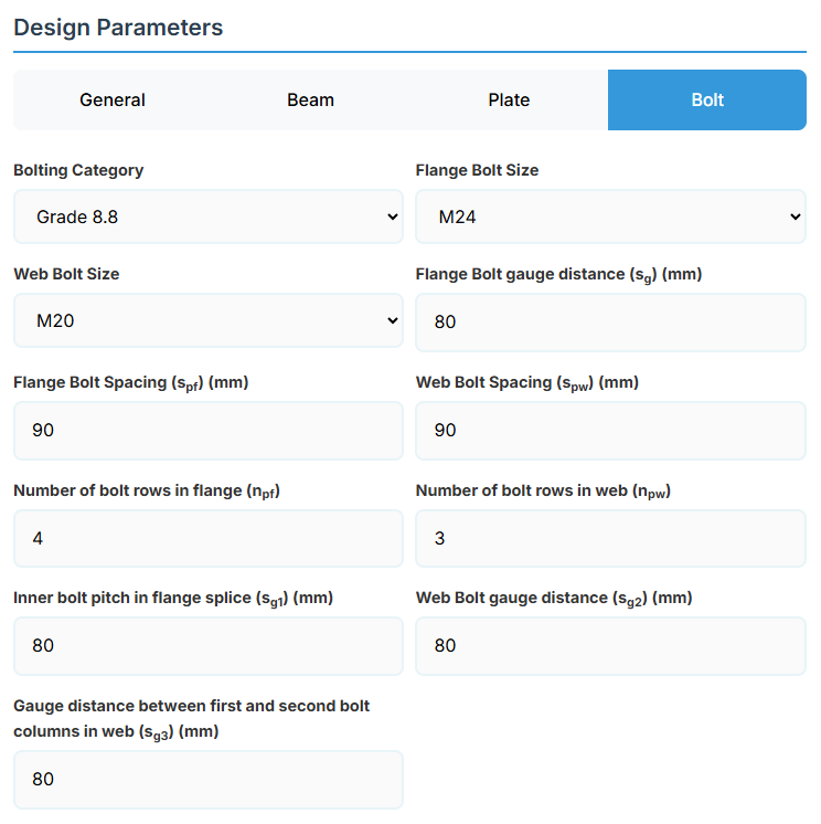
5. Bolt Configuration
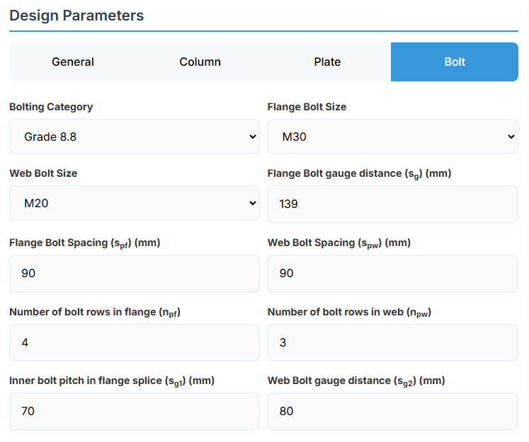
Bolt Properties
- Bolting Category: Class 8.8 - High-strength bolts with 830 MPa tensile strength.
-
Flange Bolt Size:
-
Web Bolt Size:
Bolt Layout
- Flange Bolt Gauge Distance (sg): Gauge in mm.
- Flange Bolt Spacing (spf): Spacing between flange bolts in mm.
- Web Bolt Spacing (spw): Spacing between web bolts in mm.
- Number of Bolt Rows in Flange (npf): Number of rows.
- Number of Bolt Rows in Web (npw): Number of rows.
- Inner Bolt Pitch in Flange Splice (sg1): Pitch in mm.
- Web Bolt Gauge Distance (sg2): Gauge in mm.
↑ Back to Top
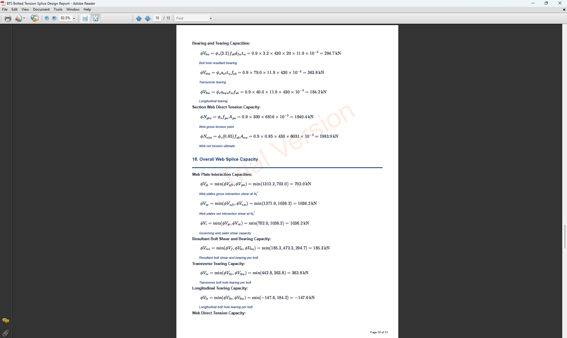
Bolted Tension Splice Design
1. Overview
The Bolted Tension Splice Design module provides a comprehensive approach for designing bolted tension splices in accordance with SCNZ 14.1-2007 Standard. It possesses design capacity to satisfy gravity and seismic design actions derived from relevant design or over-strength actions of primary members of seismic resisting frames. The splices are located away from potential seismic yielding regions of the member and maintain ductile performance under fire restraint conditions.
 ↑ Back to Top
2. General Setup
Project Information
This section captures essential metadata that will appear in your final design documentation.
- Project Name: Enter the name of the project. This helps identify the design file and appears in reports.
- Designer: The name of the person responsible for the connection design.
- Description: A brief overview of the connection design purpose or scope.
Connection Configuration
-
Splice Type: Select the type of bolted tension splice:
-
Contact Surface Type: Select the surface type for slip factor calculation:
- Unpainted Steel: Slip factor μs = 0.45 (default).
- Inorganic Zinc Silicate: Slip factor μs = 0.5.
- Alkyd Primer: Slip factor μs = 0.11.
Loading Parameters
- Design Shear Force (V*): The primary design shear force in kN.
- Design Bending Moment (M*): The primary design bending moment in kN.m.
- Design Axial Tension Nt* (kN): The design axial tension load in kN.
↑ Back to Top
3. Beam Properties
Section Type:
The application provides a comprehensive library of Australian and New Zealand standard sections. Per SCNZ 14.1, design strength limits vary based on section type (HR vs Welded). Section properties are automatically calculated from standard tables or user inputs. Doubly symmetrical I sections only.
- UB (Universal Beam) - Grades G350 and G300+
- UC (Universal Column) - Grades G350 and G300+
-
CWB (Custom Welded Beam) - Various grades.
- TFB (Tapered Flange Beam) - Grades G350 and G300+
- PB (Perimeter Welded Beams) - Grade G300M
- EB (Equivalent Welded Beams) - Grade G300M
- HB (Heavy Welded Beams) - Grade G300M
- HCB (High Capacity Beams) - Grade G300M
- HCBC (High Capacity Beam-Columns) - Grade G300M
- HCC (High Capacity Columns) - Grade G300M
- HP (Welded 'H' Piles) - Grade G300M
- NB (Narrow Welded Beams) - Grade G300M
- BP (Welded Bearing Piles) - Grade G300M
- SB (Standard Welded Beams) - Grade G300M
- SC (Standard Welded Columns) - Grade G300M
- LB (Light Welded Beams) - Grade G300M
- WS (Wide Sections) - Grade G300M
Section: Automatically populated based on the selected section type. The user can then select a specific section from the list.
When CWB is selected, manual inputs for depth (d), flange width (bf), flange thickness (tf), and web thickness (tw) become available.
↑ Back to Top
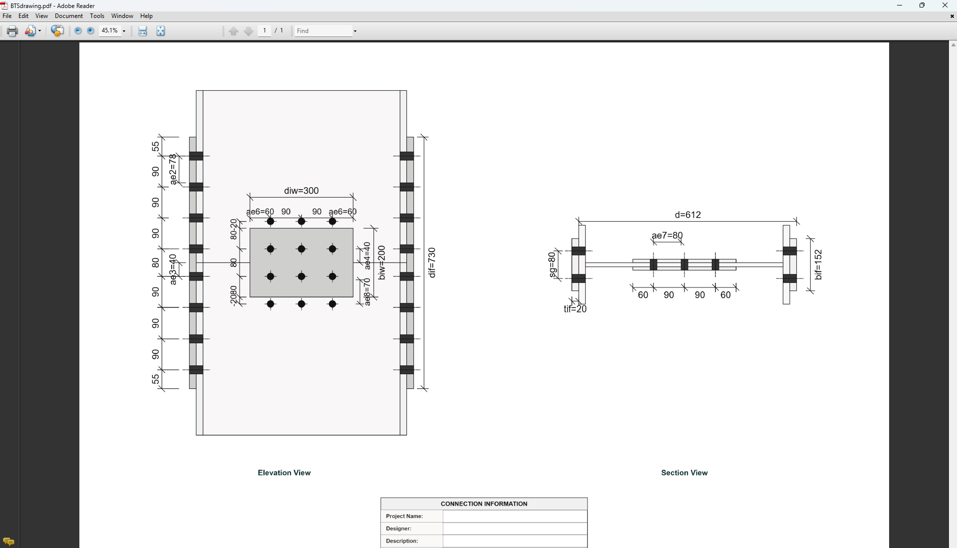
4. Plate Details
Flange Plate
- Flange Plate Steel Grade: G250, G300, G400, G350, or G450.
- Flange Plate Depth (dif): Depth of the flange plate in mm.
- Flange Plate Width (bif): Width of the flange plate in mm.
- Flange Plate Thickness (tif): Thickness of the flange plate in mm.
- Doubler Flange Plate Width (bi2): Width of the doubler flange plate in mm (for BTS2).
Web Plate
- Web Plate Steel Grade: G250, G300, G400, G350, or G450.
- Web Plate Depth (diw): Depth of the web plate in mm.
- Web Plate Width (biw): Width of the web plate in mm.
- Web Plate Thickness (tiw): Thickness of the web plate in mm.
↑ Back to Top
5. Bolt Configuration
Bolt Properties
- Bolting Category: Class 8.8 - High-strength bolts with 830 MPa tensile strength.
-
Flange Bolt Size:
-
Web Bolt Size:
Bolt Layout
- Flange Bolt Gauge Distance (sg): Gauge in mm.
- Flange Bolt Spacing (spf): Spacing between flange bolts in mm.
- Web Bolt Spacing (spw): Spacing between web bolts in mm.
- Number of Bolt Rows in Flange (npf): Number of rows.
- Number of Bolt Rows in Web (npw): Number of rows.
- Inner Bolt Pitch in Flange Splice (sg1): Pitch in mm.
- Web Bolt Gauge Distance (sg2): Gauge in mm.
- Gauge Distance between First and Second Bolt Columns in Web (sg3): Gauge in mm.
↑ Back to Top
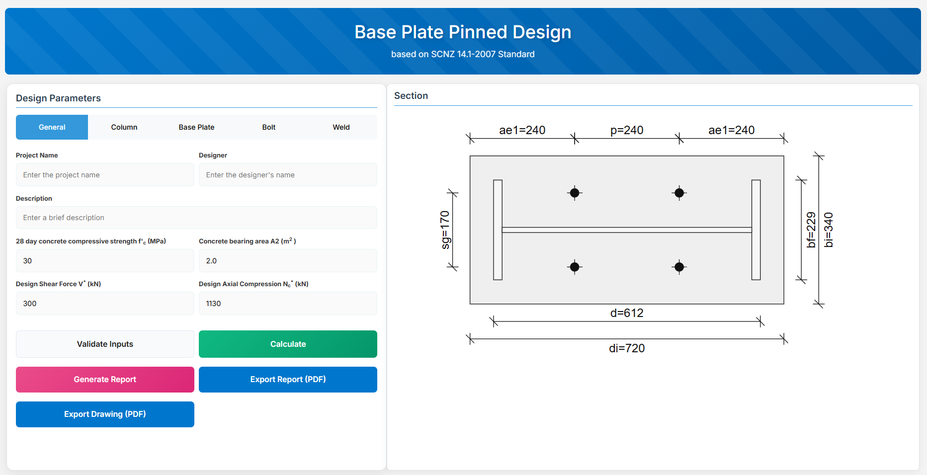
Base Plate Pinned Design
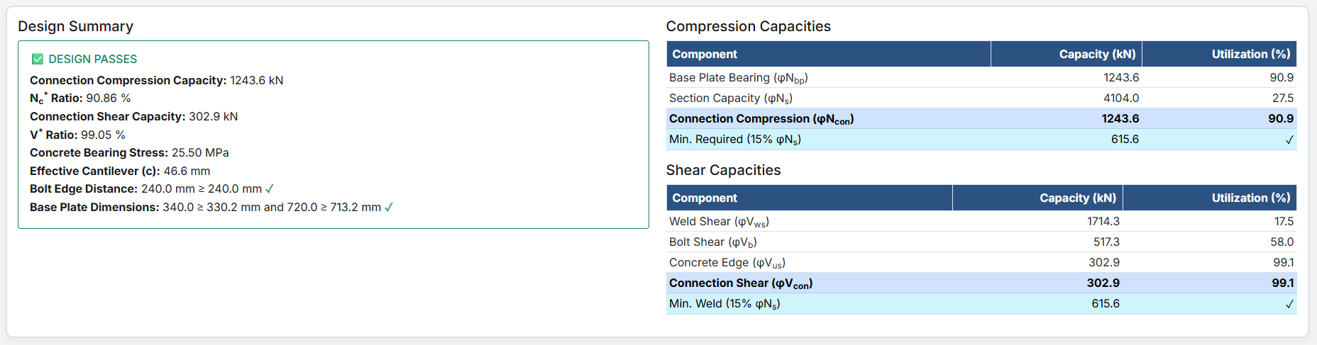
1. Overview
The Base Plate Pinned Design module provides a comprehensive approach for designing pinned base plates in accordance with SCNZ 14.1-2007 Standard. It possesses design axial compression and shear capacity to support ultimate limit state design loads. To have sufficient lateral shear resistance provided by the holding down bolts to provide full twist and lateral translation restraint for the axial design load. The connection is assumed to be nominally pinned. All columns are assumed to be prepared for full end contact bearing onto the base-plate in accordance with NZS3404:1997.
 ↑ Back to Top
2. General Setup
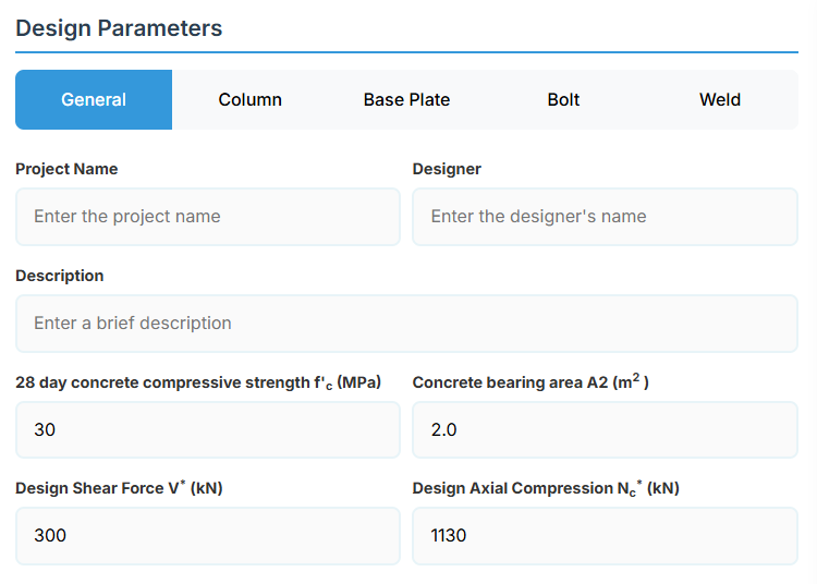
Project Information
This section captures essential metadata that will appear in your final design documentation.
- Project Name: Enter the name of the project. This helps identify the design file and appears in reports.
- Designer: The name of the person responsible for the connection design.
- Description: A brief overview of the connection design purpose or scope.
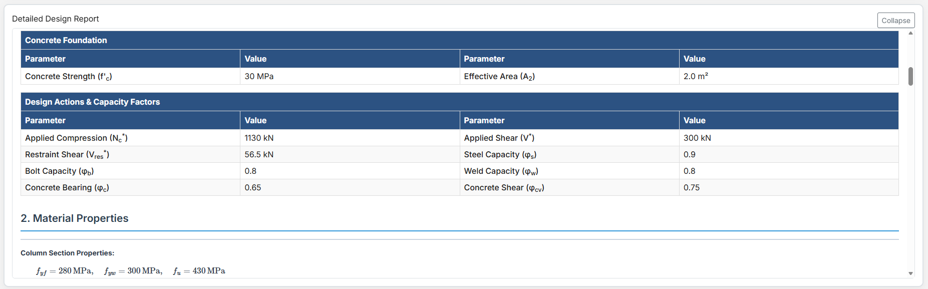
Loading and Foundation Parameters
- 28 day Concrete Compressive Strength f'c (MPa): The concrete strength at 28 days.
- Concrete Bearing Area A2 (m2): The bearing area of the concrete foundation.
- Design Shear Force (V*): The primary design shear force in kN.
- Design Axial Compression Nc* (kN): The design axial compression load.
↑ Back to Top
3. Column Properties
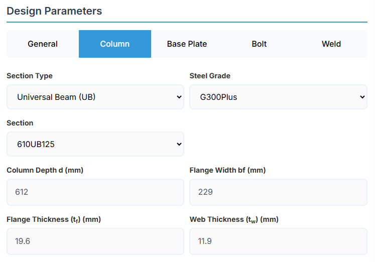
Section Type:
The application provides a comprehensive library of Australian and New Zealand standard sections. Per SCNZ 14.1, design strength limits vary based on section type (HR vs Welded). Section properties are automatically calculated from standard tables or user inputs.
- UB (Universal Beam) - Grades G350 and G300+
- UC (Universal Column) - Grades G350 and G300+
- CWB (Custom Welded Beam) - Various grades.
- CHS (Circular Hollow Section) - Various grades.
- RHS (Rectangular Hollow Section) - Various grades.
- SHS (Square Hollow Section) - Various grades.
- PFC (Parallel Flange Channel) - Various grades.
- TFB (Tapered Flange Beam) - Grades G350 and G300+
- PB (Perimeter Welded Beams) - Grade G300M
- EB (Equivalent Welded Beams) - Grade G300M
- HB (Heavy Welded Beams) - Grade G300M
- HCB (High Capacity Beams) - Grade G300M
- HCBC (High Capacity Beam-Columns) - Grade G300M
- HCC (High Capacity Columns) - Grade G300M
- HP (Welded 'H' Piles) - Grade G300M
- NB (Narrow Welded Beams) - Grade G300M
- BP (Welded Bearing Piles) - Grade G300M
- SB (Standard Welded Beams) - Grade G300M
- SC (Standard Welded Columns) - Grade G300M
- LB (Light Welded Beams) - Grade G300M
- WS (Wide Sections) - Grade G300M
Section: Automatically populated based on the selected section type. The user can then select a specific section from the list.
When CWB is selected, manual inputs for depth (d), flange width (bf), flange thickness (tf), and web thickness (tw) become available.
↑ Back to Top
4. Base Plate Details
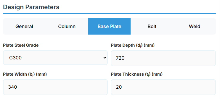
Base Plate Material and Geometry
Define the base plate parameters. These directly affect the bearing capacity and shear strength.
- Plate Steel Grade: G250, G300, G400, G350, or G450.
- Plate Depth (di): Depth of the base plate in mm.
- Plate Width (bi): Width of the base plate in mm.
- Plate Thickness (ti): Thickness of the base plate in mm.
↑ Back to Top
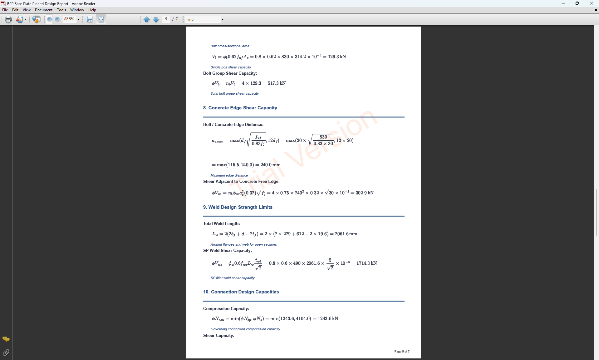
5. Bolt Configuration
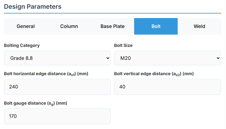
Bolt Properties
- Bolting Category:
- Class 4.6 - With 400 MPa tensile strength.
- Class 8.8 - High-strength bolts with 830 MPa tensile strength.
-
Bolt Size:
Bolt Layout
- Bolt Horizontal Edge Distance (ae1): Horizontal edge distance in mm.
- Bolt Vertical Edge Distance (ae2): Vertical edge distance in mm.
- Bolt Gauge Distance (sg): Gauge in mm.
↑ Back to Top
6. Weld Details
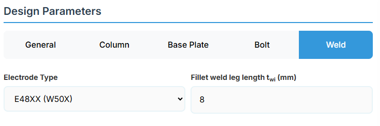
Weld Configuration
Define the weld parameters. The welds of the column to the base plate are SP welds, designed to resist the prescribed design action and transfer a minimum of 15% of column section capacity.
-
Electrode Type:
- E41XX (W40X): 410 MPa yield strength.
- E48XX (W50X): 490 MPa yield strength (default).
- Fillet Weld Leg Length twi (mm): Size of the fillet weld in mm.
↑ Back to Top
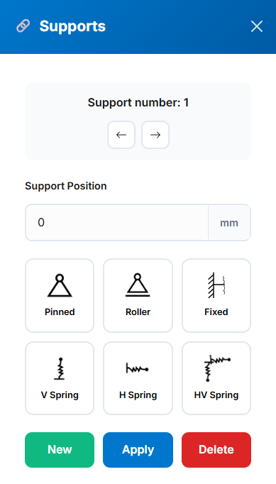
 Pinned (translational fixed, rotational free)
 Roller (vertical fixed, horizontal free)
 Fixed (all DOF restrained; ends only)
 Vertical Spring (user-defined stiffness)
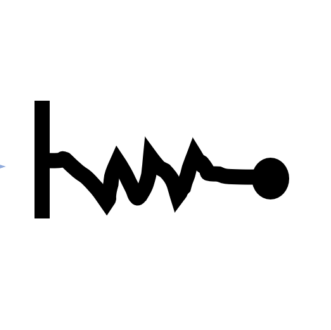 Horizontal Spring (user-defined stiffness)
 Combined Horizontal/Vertical Spring (user-defined stiffness)